Multi step transmission

a transmission and multi-step technology, applied in mechanical equipment, transportation and packaging, gear sets, etc., can solve the problems of low rotational speed of shafts, shift elements, and planetary gear sets, and achieve the effect of improving efficiency, reducing construction expenditure and overall size, and reducing construction costs

Inactive Publication Date: 2012-07-31
ZF FRIEDRICHSHAFEN AG
View PDF47 Cites 92 Cited by
  • Summary
  • Abstract
  • Description
  • Claims
  • Application Information

AI Technical Summary

Benefits of technology

[0014]The objective of the present invention is to propose a multi step transmission of the initially described type, which features nine forward gears and at least one reverse gear, with a sufficient transmission ratio, in which the construction expenditure and the overall size, in particular the overall length and weight, are optimized, and additionally, in which efficiency is improved with respect to drag losses and gearing losses. In addition, in the multi step transmission according to the invention, minimal support moments should be exerted on the shift elements. According to the invention, the transmission should be particularly suited for a front transverse construction.
[0021]The embodiment of the multi step transmission, according to the invention, results in transmission ratios that are particularly suitable for passenger vehicles, and in a greater overall gear ratio of the multi step transmission, thereby improving driving smoothness and significantly reducing fuel consumption.
[0022]Furthermore, construction expenditure is significantly reduced with the multi step transmission, according to the invention, due to a small number of shift elements. According to the invention, the multi step transmission offers the advantage of performing the start-up with a hydrodynamic converter, an external start-up clutch, or even with other suitable external start-up elements. It is also conceivable to perform the start-up using a start-up element integrated into the transmission. Preferably, a shift element that is actuated in the first forward gear and in the reverse gear is suitable.
[0023]Moreover, the multi step transmission, according to the invention, results in good efficiency in the main drive gears with respect to drag losses and gearing losses.
[0024]Furthermore, low moments occur in the shift elements and in the planetary gear sets of the multi step transmission, thereby advantageously reducing wear in the multi step transmission. In addition, the low moments make it possible to utilize correspondingly low dimensions, thereby reducing the necessary installation space and related costs. Furthermore, the rotational speeds of the shafts, shift elements, and planetary gear sets are low.

Problems solved by technology

Furthermore, the rotational speeds of the shafts, shift elements, and planetary gear sets are low.

Method used


Image

  • Multi step transmission
  • Multi step transmission
  • Multi step transmission

Examples


Embodiment Construction

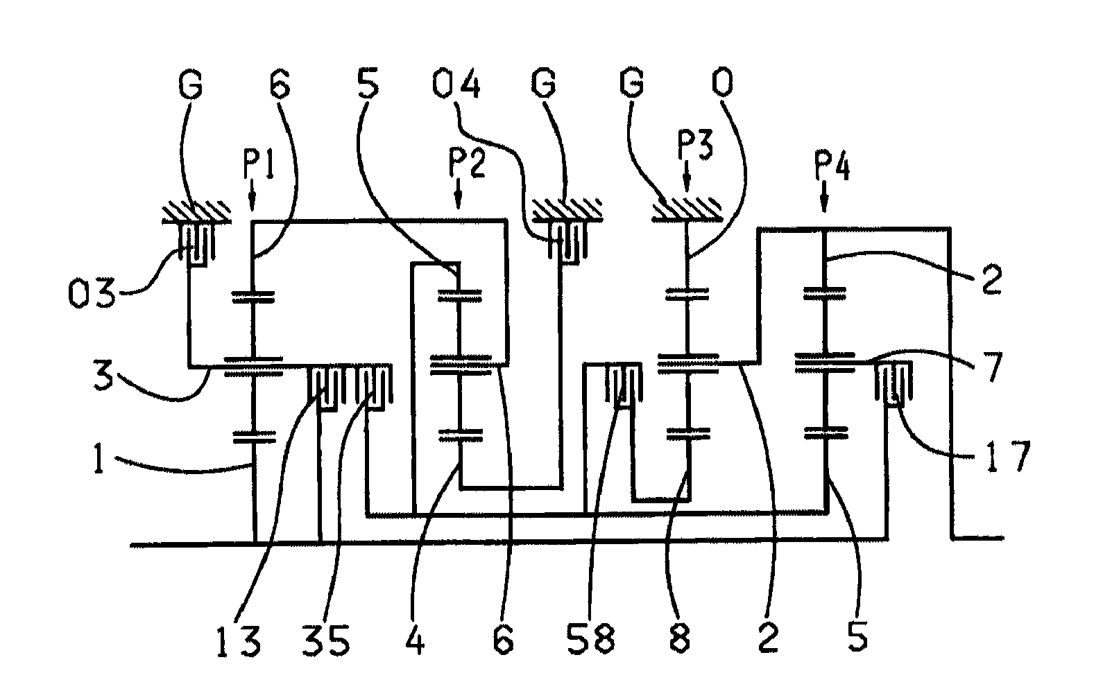
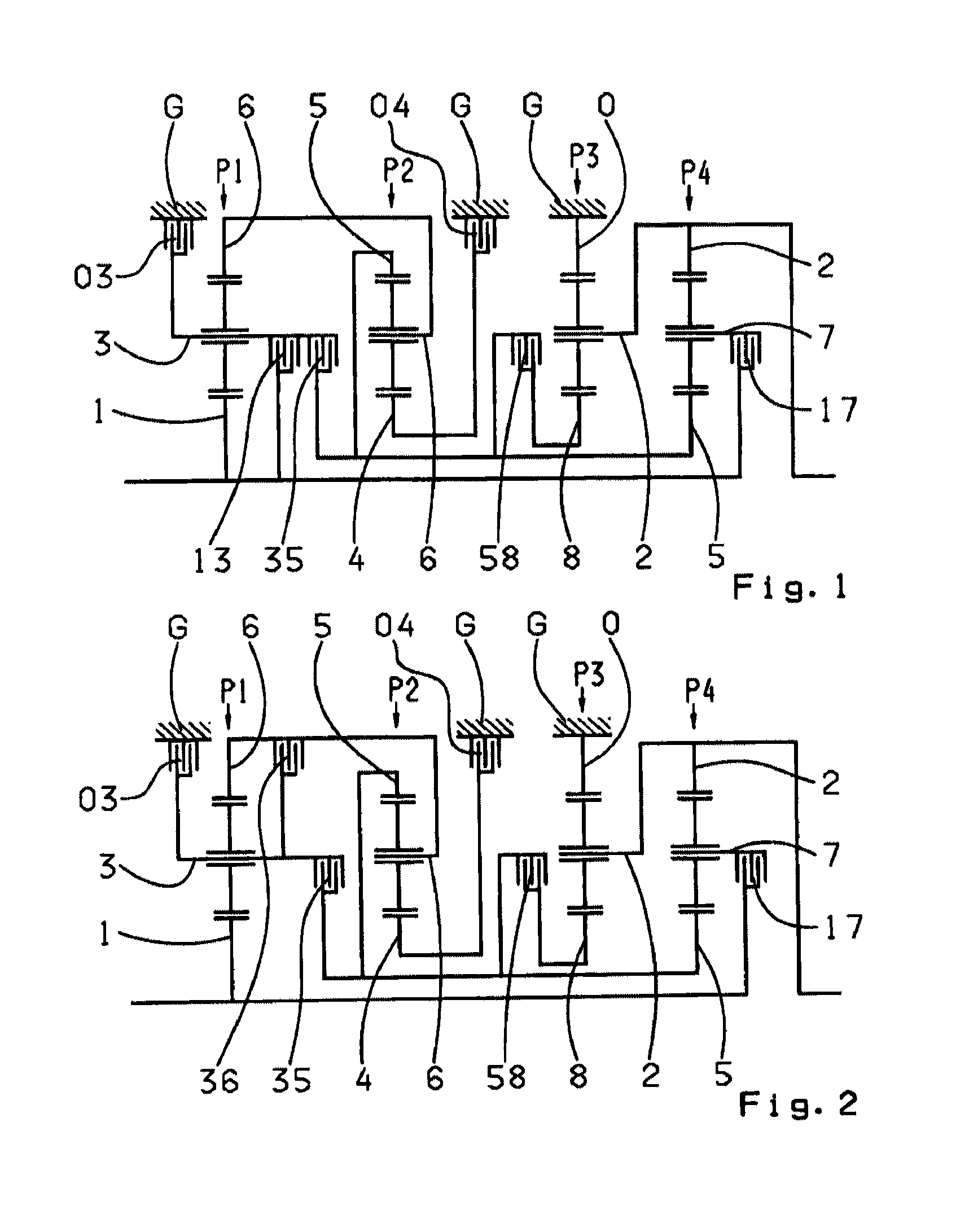
[0030]FIG. 1 shows a multi step transmission, according to the invention, which has a drive shaft 1, an output shaft 2, and four planetary gear sets P1, P2, P3 and P4, which are arranged in a housing G. Planetary gear sets P1, P2, P3 and P4, in the example shown in FIG. 1, are designed as minus planetary gear sets. According to the invention, at least one planetary gear set can be implemented as a plus planetary gear set, if the carrier and ring gear connection are switched and, simultaneously, the value of the stationary transmission ratio is increased by 1 in comparison to the embodiment as a minus planetary gear set.

[0031]In the embodiment shown, the planetary gear sets, viewed axially, are arranged in the sequence P1, P2, P3 and P4.

[0032]As depicted in FIG. 1, six shift elements are provided, namely, two brakes, 03, 04, and four clutches 13, 35, 17 and 58. The spatial disposition of the shift elements can be arbitrary, and is only limited by the dimensions of the outer design. T...


PUM


Abstract

A multi step transmission comprising gear sets, shafts and shift elements. The sun gear of set (P1) couples drive shaft (1). The carrier of set (P1) couples shaft (3) which couples, via brake (03), housing (G). Shaft (3) couples shaft (1), via clutch (13), and shaft (5) via clutch (35). Shaft (5) couples the ring and sun gears of sets (P2, P4) respectively, and shaft (8), which couples the sun gear of set (P3), via clutch (58). Shaft (1) couples shaft (7) which couples, via clutch (17), the carrier of set (P4). Shaft (6) couples the ring gear of set (P1) and the carrier of set (P2). The sun gear of set (P2) couples shaft (4) which couples, via brake (04), housing (G). The ring gear of set (P3) couples housing (G). Output shaft (2) couples the ring gear and carrier of sets (P4, P3) respectively.

Description

[0001]This application claims priority from German Application No. 10 2009 028 713.2 filed Aug. 20, 2009.FIELD[0002]The present invention relates to a multi step transmission of a planetary design, in particular an automatic transmission for a motor vehicle.BACKGROUND[0003]According to the prior art, automatic transmissions, particularly for motor vehicles, comprise planetary gear sets that are shifted using friction elements or shift elements such as clutches and brakes, and typically are connected to a start-up element, such as a hydrodynamic torque converter or a fluid coupling, that is subject to a slip effect and is optionally provided with a lock-up clutch.[0004]Such an automatic transmission is known, for example, from the applicant's DE 199 49 507 A1, according to which two non-shiftable front-mounted gear sets are provided on the drive shaft and generate two rotational speeds on the output side, which, in addition to the rotational speed of the drive shaft, can be selective...

Claims


Application Information

Patent Timeline
Patent Type & Authority Patents(United States)
IPC IPC(8): F16H3/44
CPCF16H3/66F16H2200/0065F16H2200/2012F16H2200/2046F16H2200/2097
Inventor GUMPOLTSBERGER, GERHARDSIBLA, CHRISTIANBECK, STEFANHAUPT, JOSEFBAUKNECHT, GERTZIEMER, PETER
Owner ZF FRIEDRICHSHAFEN AG
Why Eureka
Try Eureka