Adjustable motorized screen mount

a motorized screen and adjustment technology, applied in the direction of machine supports, toothed gearings, domestic objects, etc., can solve the problems of visual exposure of the actuator, operator may find the rotary speed either too slow or too fast, and it is difficult to achieve a slow and constant motion of the screen bracket without using a large or complicated transmission mechanism. , to achieve the effect of simple construction and few moving parts

Inactive Publication Date: 2011-08-18
FIEDLER INNOVATIONS INT
View PDF13 Cites 4 Cited by
  • Summary
  • Abstract
  • Description
  • Claims
  • Application Information

AI Technical Summary

Benefits of technology

[0007]It is an object of the present invention to provide an adjustable, motorized screen mount which is compact, simple in its construction and comprises few moving parts; which can be adjusted by hand as well as by a motor; which is capable of carrying and mo

Problems solved by technology

The spacing between the wall and the screen in the retracted position, as well as the visual exposure of the actuator as the mount is opened, may be undesired from an aesthetic point of view.
Further, as the speed of the rotation of the screen bracket will vary across the turning range of the bracket, an operator may find the rotary speed to be either too slow or too fast depending on the position of the bracket.
As a typical electric motor operates at a constant, high rotary speed, i

Method used


Image

  • Adjustable motorized screen mount
  • Adjustable motorized screen mount
  • Adjustable motorized screen mount

Examples


Embodiment Construction

[0025]In FIGS. 1-4, like reference numerals refer to like elements, and for clarity, all reference numerals and / or elements are not shown in all figures.

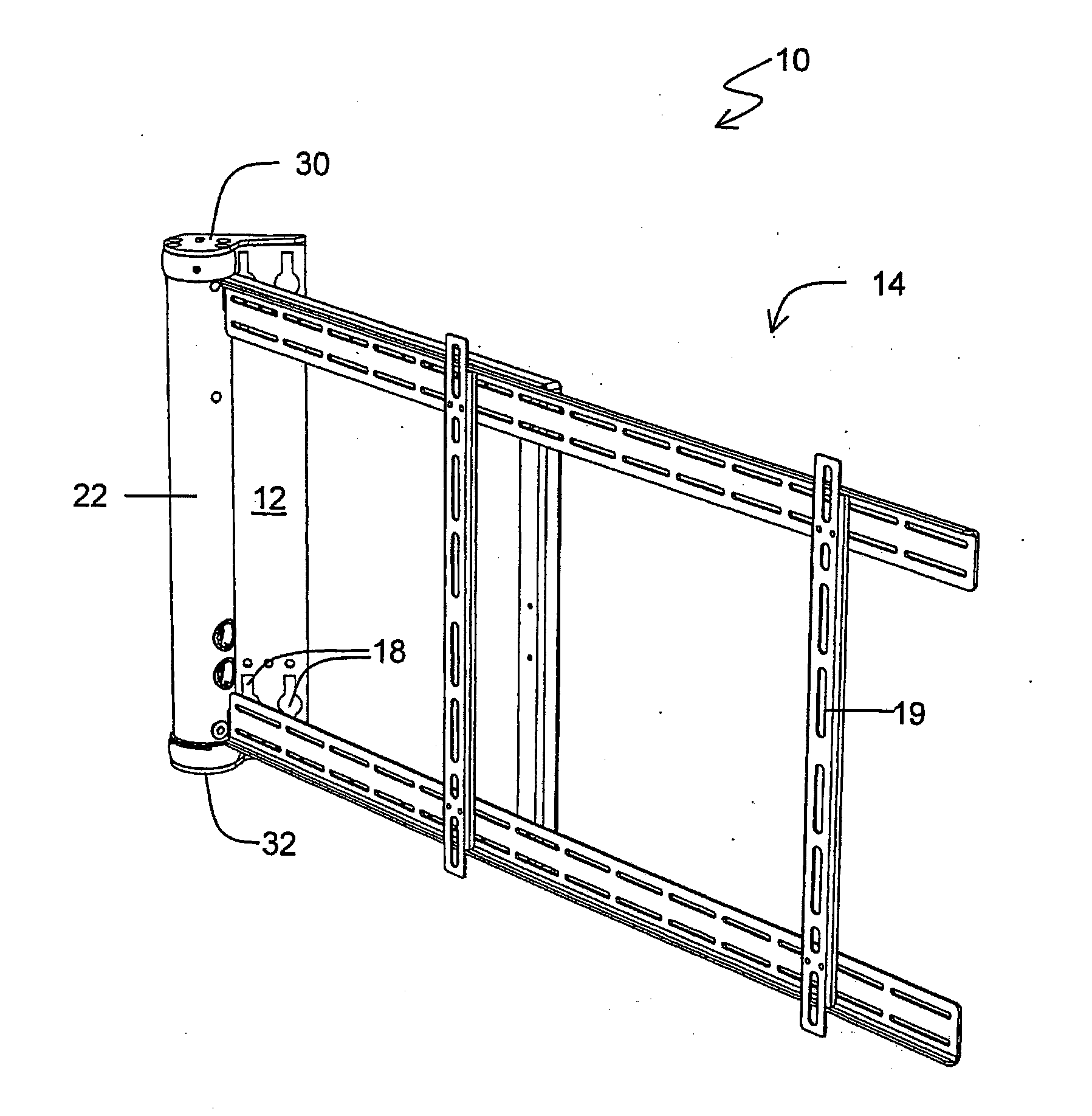
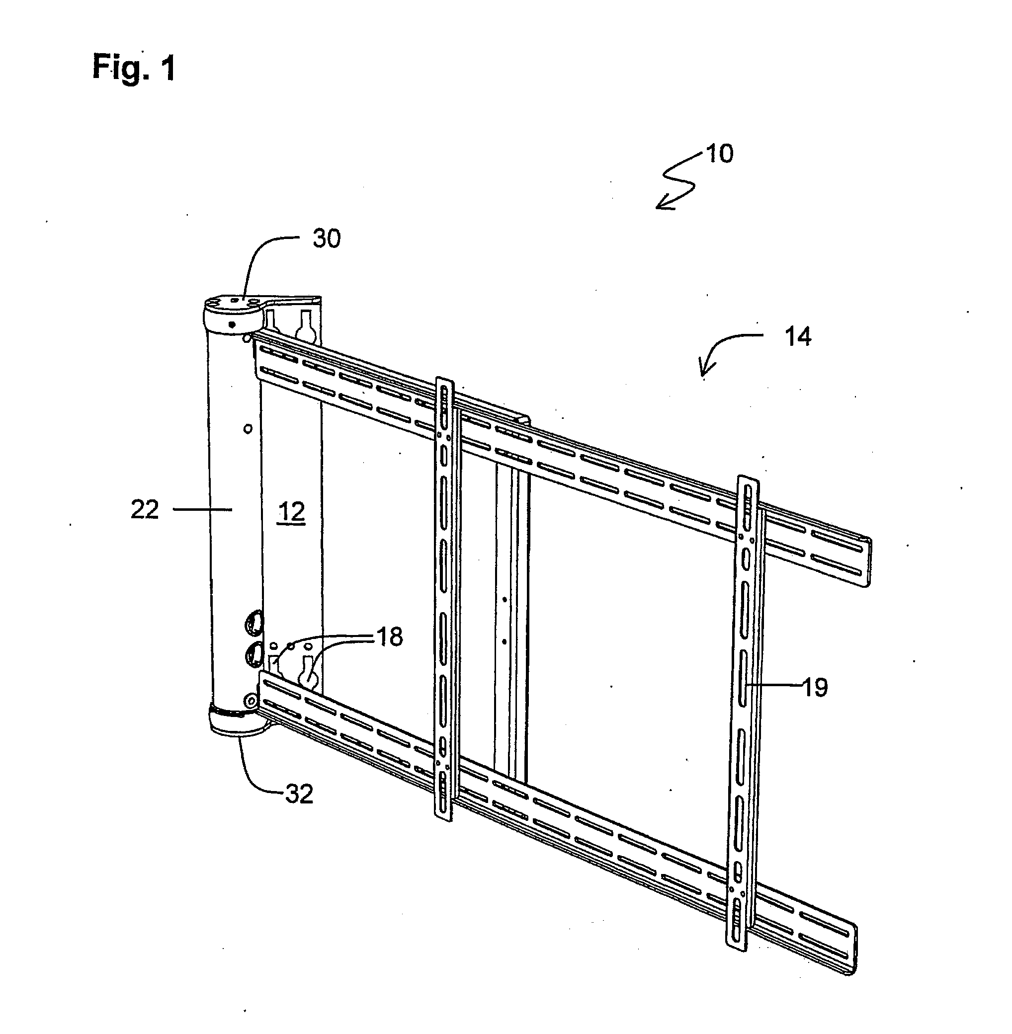
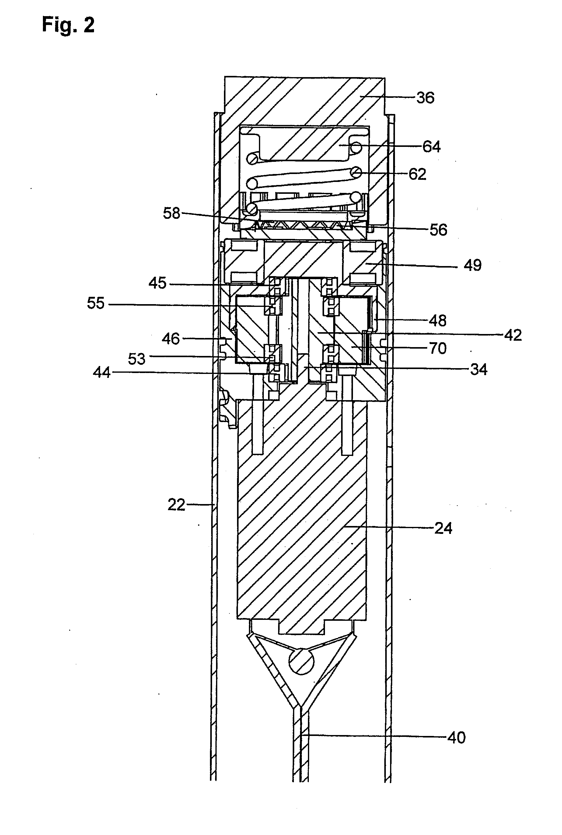
[0026]FIG. 1 illustrates schematically an exemplary embodiment of an adjustable motorized screen mount 10, which is adapted for mounting a screen onto a vertical wall or a ceiling. The screen mount 10, which in the figures is oriented to be mounted vertically on a wall, but might as well be mounted horizontally to a ceiling, comprises a stand 12 and a bracket 14. The stand 12 has a flat surface, which is provided with mounting holes 18 for fixing the stand 12 to the wall by means of screws (not shown). The bracket 14 is provided with mounting holes 19 for fixing a screen (not shown) to the bracket 14 by means of screws (not shown). Further, the bracket 14 is connected to the stand 12 by means of a “motorized hinge”, i.e. a tubular housing 22 containing a transmission that is further described with reference to FIGS. 2-4.

[0027]The tr...


PUM


Abstract

The invention relates to an adjustable motorized screen mount comprising a stand (12), adapted to be placed on a floor or attached to a wall or a ceiling; a bracket (14), adapted to be attached to a screen; and a motor, arranged to rotate a motor output shaft such that, upon rotation of the motor shaft, the rotary motion is transmitted, via a mechanical transmission comprising a multi-stage hypocycloid reduction geat train, to a transmission output shaft which moves the bracket (14) relative to the stand 912).

Description

FIELD OF THE INVENTION[0001]The present invention relates to an adjustable motorized screen mount comprising a stand, adapted to be placed on a floor or attached to a wall or a ceiling; a bracket, adapted to be attached to a screen; and a motor, arranged to rotate a motor output shaft such that, upon rotation of the motor shaft, the rotary motion is transmitted, via a mechanical transmission, to a transmission output shaft which moves the bracket relative to the stand.BACKGROUND OF THE INVENTION[0002]For having the best viewing comfort when watching the screen of a television set, a video monitor, a computer monitor or the like, a suitable viewing angle should be selected, i.e. the screen and the viewer should be positioned in such a relation to each other that the perceived watching experience of the viewer be optimized. For a viewer to be able to watch the screen from different locations at different occasions, it is desirable to be able to turn the screen for an optimum viewing e...

Claims


Application Information

Patent Timeline
IPC IPC(8): F16M11/04F16H1/28
CPCF16M11/08F16M11/10F16M13/027F16M13/02F16M11/18
Inventor FIEDLER, JOAKIM
Owner FIEDLER INNOVATIONS INT
Why Eureka
Try Eureka