Imaging lens and image pickup device

a technology of image pickup and lens, applied in the field of imaging lenses, can solve the problems of hardly obtaining high image quality, difficult miniaturization, and increasing the length of the entire length, and achieve the effects of compact and fast, good image formation performance, and hardly deteriorating performan

Active Publication Date: 2009-08-20
TIANJIN OFILM OPTO ELECTRONICS CO LTD
View PDF6 Cites 17 Cited by
  • Summary
  • Abstract
  • Description
  • Claims
  • Application Information

AI Technical Summary

Benefits of technology

[0014]According to the imaging lens of the present invention, in a lens system including four lenses as a whole, since the lens elements respectively have proper structures, the lens system is easily realized that maintains a good image formation performance and is compact and fast and whose performance is hardly deteriorated even when the position of an aperture diaphragm is changed. Especially, when the conditional expressions (3) and (4) are satisfied and the power of the third lens is made to be relatively stronger than that of a usual imaging lens composed of four lenses, an entire length is easily decreased to obtain a fast lens system that has few field curvatures. Further, since the aspheric shapes of both the surfaces of the third lens are configured as special shapes, even when a small aperture diaphragm (another stop) is arranged, the occurrence of the field curvatures is suppressed.
[0017]According to the imaging lens of the present invention, in the lens system including the four lenses as a whole, the structures of the lens elements are respectively optimized, the power of the third lens is especially made to be relatively stronger than that of the usual imaging lens including the four lenses and the aspheric shapes of both the surfaces of the third lens are configured as the special shapes. Accordingly, the lens system can be realized that maintains the good image formation performance and is compact and fast and whose performance is hardly deteriorated even when the position of the aperture diaphragm is changed.

Problems solved by technology

However, in an imaging lens described in the above-described patent documents, since a second lens has a concave shape directed to an object side, an entire length is increased so that a miniaturization is difficult.
Further, since many field curvatures are generated, a problem arises that a high image quality is hardly obtained.
Therefore, the performances of the field curvatures are liable to be deteriorated.
However, in a compact image pickup device, an aperture diaphragm is frequently a fixed diaphragm in view of a mechanical problem and a problem of cost.
Accordingly, when an optical design that considers only an ordinary fast state is drawn, the image formation performance is liable to be deteriorated (especially, the field curvatures are deteriorated) under the state that the small aperture diaphragm is arranged, so that the lens system is insufficient in its performance.

Method used


Image

  • Imaging lens and image pickup device
  • Imaging lens and image pickup device
  • Imaging lens and image pickup device

Examples


examples

[0119]Now, specific numerical examples of the imaging lens according to this embodiment will be described below. A plurality of numerical examples will be collectively described below.

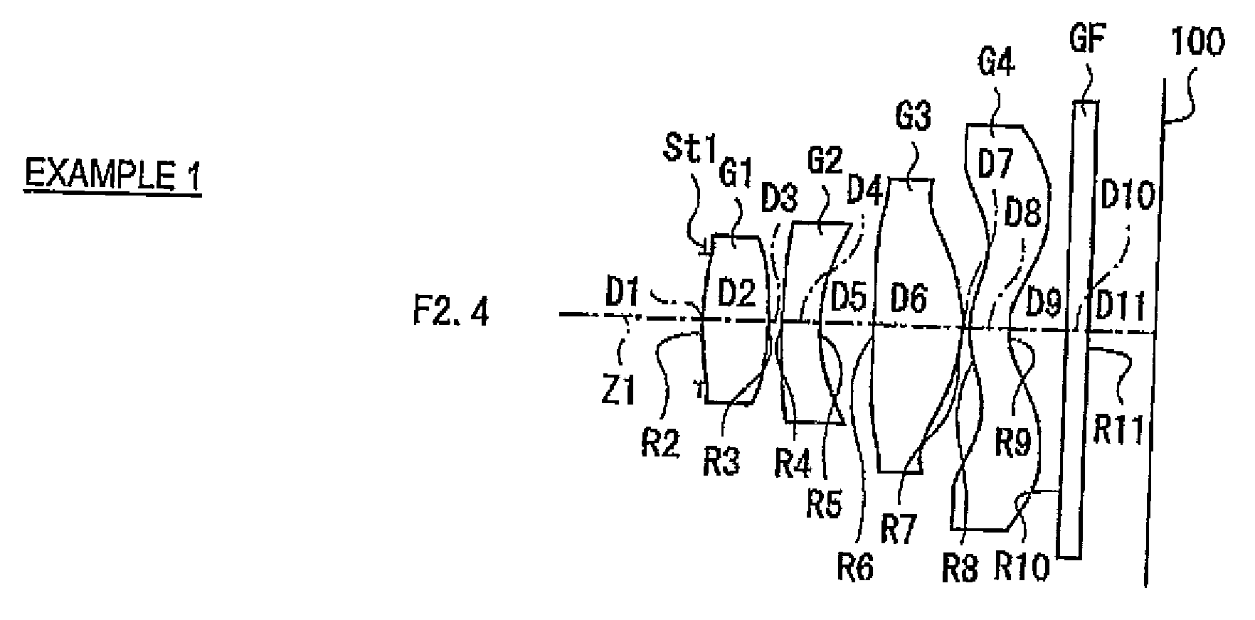
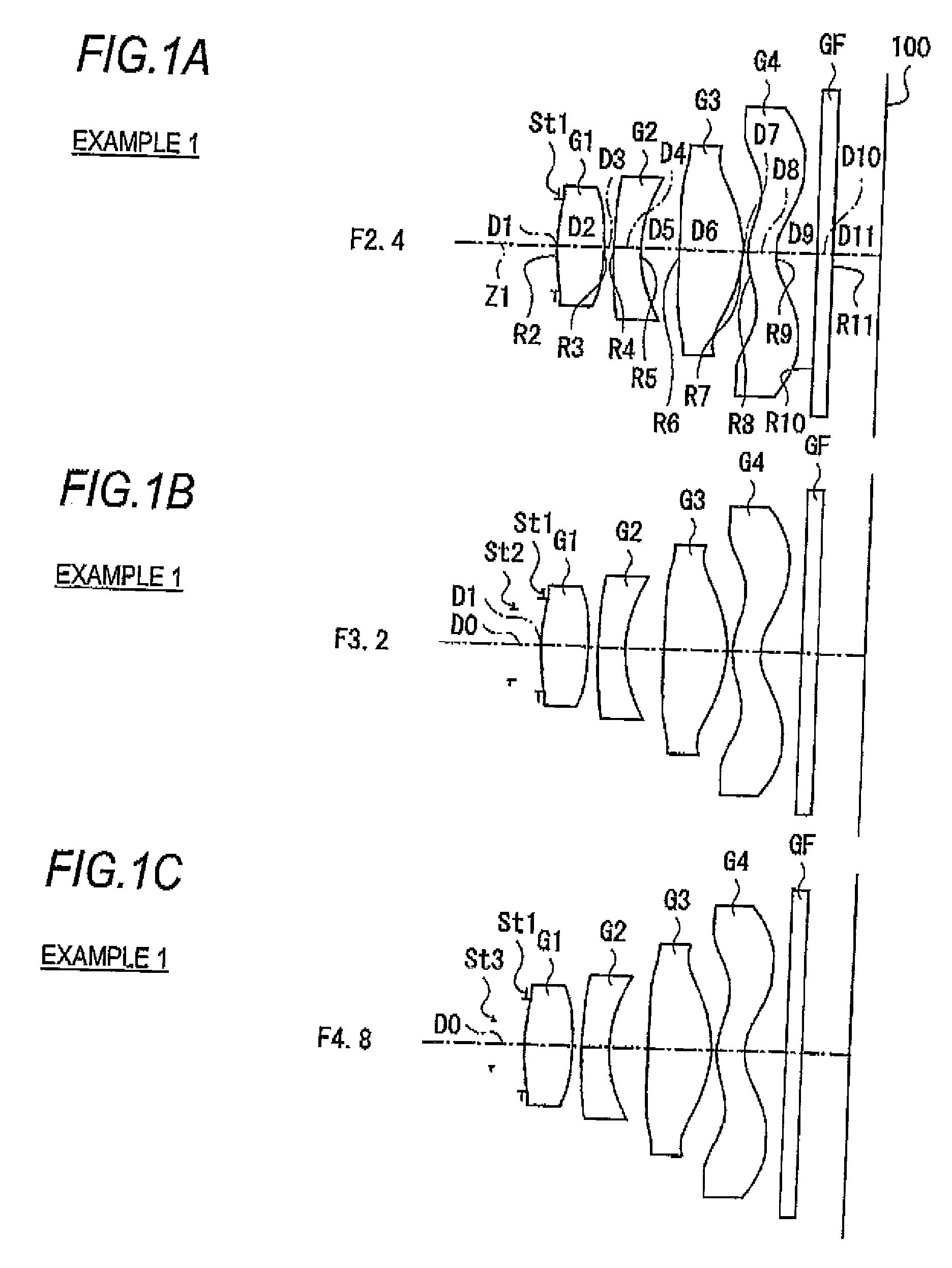
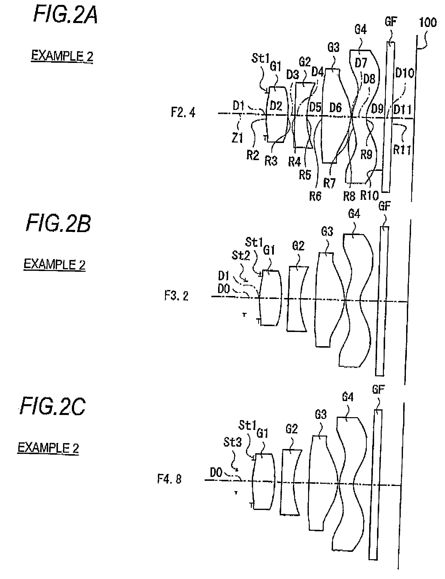
[0120]FIGS. 10A and 10B and FIG. 11 show specific lens data corresponding to the structure of the imaging lens shown in FIGS. 1A to 1C, Especially, FIG. 10 A shows basic lens data thereof and FIG. 11 shows data of the aspheric surface. Further, FIG. 10B shows data of the aperture diaphragm. In a column of a surface number Si in the lens data shown in FIG. 10A, the number of an i th surface to which a symbol is attached in such a way that a surface of a component nearest to the object side in the imaging lens according to a first example is designated as a first surface, and the number of the surface is sequentially increased as the surface comes nearer to the image side. In a column of a curvature radius Ri, a value (mm) of the curvature radius of the i th surface from the object side is shown correspo...


PUM


Abstract

An imaging lens includes in order from an object side, a stop and a first lens to a fourth lens. Both the surfaces of a third lens have surfaces including at least one inflection point, and an inclination of each surface at the terminal end part of a periphery within an effective diameter collapses toward the image side. And 0.1<D3 / D4<2.0, νd1−νd2>25, 0.4<f1 / f3<1.6 and 0.3<f / f3<1.5 are satisfied, where D3 is an air space on an optical axis between the first lens and the second lens, D4 is a central thickness of the second lens, νd1 and νd2 are Abbe numbers of the first lens and the second lens, f1 and f3 are focal lengths of the first lens and the third lens and f is a focal length of an entire system.

Description

CROSS-REFERENCE TO RELATED APPLICATIONS[0001]This application is based on and claims priority under 35 USC 119 from Japanese Patent Application No. 2008-033397 filed Feb. 14, 2008; the entire contents of which are incorporated herein by reference.BACKGROUND[0002]1. Technical Field[0003]The present invention relates to an imaging lens that forms an optical image of an object to be shot on an image pickup element such as a CCD (Charge Coupled Device) or a CMOS (Complementary Metal Oxide Semiconductor) and an image pickup device such as a digital still camera, a portable cellular phone having a camera and an information portable terminal (PDA: Personal Digital Assistance on which the imaging lens is mounted to shoot the object to be shot.[0004]2. Related Art[0005]In recent years, with the spread of personal computers in ordinary homes, digital still cameras are rapidly popularized to which image information such as the images of shot landscapes or persons can be inputted. Further, came...

Claims


Application Information

Patent Timeline
Patent Type & Authority Applications(United States)
IPC IPC(8): G02B9/34
CPCG02B13/004G02B9/34
Inventor SHINOHARA, YOSHIKAZU
Owner TIANJIN OFILM OPTO ELECTRONICS CO LTD
Why Eureka
Try Eureka