Fixing mechanism of battery

A fixing mechanism and battery technology, applied to the structure of telephone sets, battery pack parts, circuits, etc., can solve problems such as inconvenient loading and unloading, damage to parts, manufacturing costs, and complexity

Inactive Publication Date: 2009-12-16
INVENTEC CORP
View PDF0 Cites 16 Cited by
  • Summary
  • Abstract
  • Description
  • Claims
  • Application Information

AI Technical Summary

Problems solved by technology

[0006] However, since this prior art requires the first fixing mechanism 11 and the second fixing mechanism 12 to be in the unlocked state at the same time, the battery can be installed or taken out, so no matter when the battery is installed or taken out, both hands are required to pull the first fixing mechanism at the same time. Mechanism 11 and the second fixing mechanism 12 can be released from fixing; and, when desiring to take out the battery, not only need both hands to pull the fixing mechanism that separates simultaneously to remove fixing, more must hook up the edge of battery with finger again, just can be removed smoothly The battery is installed or removed, so it is quite inconvenient to install and remove
Moreover, two fixing mechanisms are required to achieve the purpose of installing or taking out the battery, so there are relatively many and complicated components, which will not only increase the assembly man-hours, but also increase the probability of component damage and increase the manufacturing cost

Method used


Image

  • Fixing mechanism of battery
  • Fixing mechanism of battery
  • Fixing mechanism of battery

Examples


Embodiment Construction

[0051] The implementation of the present invention is described below through specific examples, and those skilled in the art can easily understand other advantages and effects of the present invention from the content disclosed in this specification.

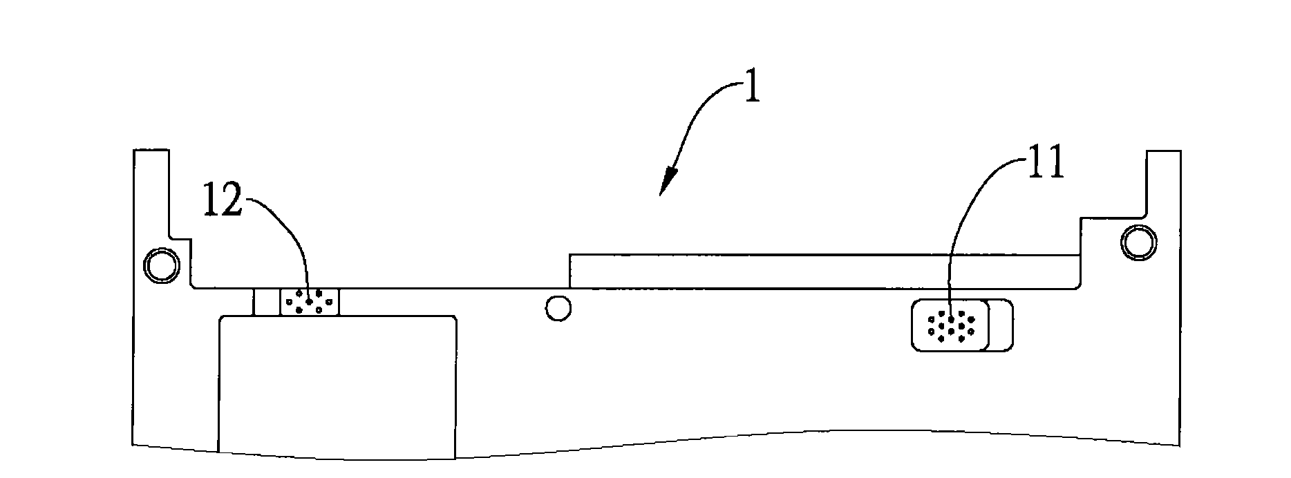
[0052] Embodiments of the present invention will be described below with reference to the accompanying drawings. It should be noted that the battery fixing mechanism of the present invention is applied to an electronic device to fix the battery to the housing groove of the electronic device, so as to facilitate the installation and disassembly of the battery. , where the electronic device can be, for example, a notebook computer, an electronic translator, a personal digital assistant (PDA), or other electronic devices that need to be equipped with batteries, and the various types, quantities and ratios of the actual implementation are not shown in the diagram As a limit, it can be changed according to the actual design needs, an...


PUM


Abstract

The invention relates to a fixing mechanism of a battery, which is used for fixing the battery to an accommodation groove of an electronic device shell, and the battery is provided with a grab and a bevel at one side of the grab. The fixing mechanism comprises a first limit part arranged at one side of the accommodation groove, an elastic limit part arranged at one side of the first limit part, a bolt-lock provided with a first positioning part and arranged corresponding to the first limit part, a second positioning part corresponding to the first positioning part and arranged at the accommodation groove, and a push button of a first fixed part correspondingly fixed at the bolt-lock, wherein the push button is linked with the first positioning part and enables the elastic component of the elastic limit part to be in a compression-free state or a compressed state, so that a buckle part moves along the bevel to fix or take out the battery.

Description

technical field [0001] The invention relates to a fixing technology of an electronic device, more specifically, to a fixing mechanism of a battery. Background technique [0002] The popularization of portable electronic devices, such as notebook computers, personal mobile phones, palm-sized personal digital assistants (PDAs), walkmans (Walkman) or satellite navigation devices (GPS), etc., makes people's daily life more convenient. At the same time, the above-mentioned portable electronic devices all have a battery installed inside, and the battery is usually a rechargeable battery that can be recharged. Therefore, the battery can be fixed to the casing of the portable electronic device when going out. The battery can be removed from the housing when not in use. Generally speaking, corresponding slots and hooks are provided between the casing and the battery to fix the battery to the casing. [0003] see Figure 1A , 1B and 1C, showing the schematic diagram of the fixing m...

Claims


Application Information

Patent Timeline
Patent Type & Authority Applications(China)
IPC IPC(8): H01M2/10H05K5/02H04M1/02G06F1/16G06F1/26H01M50/262
CPCY02E60/12Y02E60/10
Inventor 郭明亮萧丰能
Owner INVENTEC CORP
Why Eureka
Try Eureka