Motor vehicle

a motor vehicle and electric motor technology, applied in the field of motor vehicles, can solve the problems of increasing the weight and cost of the motor vehicle, the need for relativly complex mechanics, and the additional components of the electric motor, so as to achieve constant charging and discharging of energy storage devices, and implement protective functions.

Active Publication Date: 2017-05-02
AUDI AG
View PDF19 Cites 5 Cited by
  • Summary
  • Abstract
  • Description
  • Claims
  • Application Information

AI Technical Summary

Benefits of technology

[0020]It is however particularly advantageous when the crown gearwheel is connected with the driven differential element via a further coupling device, which is controlled by the control device, and in a first coupling state couples the crown gearwheel with the driven differential element and in a second coupling state separates the crown gearwheel from the driven differential element. The further coupling device enables separating the drive motor from the driven differential element and with this from the differential. This enables in particular driving the output shafts exclusively by the additional motor. This avoids the friction losses in the further drive train and losses due to the drive motor.
[0022]In a first coupling state the coupling device can couple the additional motor with the planet carrier. Hereby the drive shaft can be coupled with the ring gear, a first one of the output shafts with the at least one planet gear, and a second one of the output shafts with the sun gear. A coupling of the additional motor to the output shaft via the planet carrier enables a mechanically particularly simple coupling of the additional motor to the output shaft. This allows in particular achieving a sufficient transmission ratio between the additional motor and output shaft while at the same time using only little construction space.
[0026]In a third coupling state the coupling device can in particular separate the additional motor from the driven differential element as well as from the output shaft. In this case the additional motor is decoupled from the entire drive train. Such a decoupling from the drive train prevents on one hand an energy loss as a result of the additional motor, when the additional motor is operated neither for providing torque nor for the purpose of recuperation, and on the other hand enables implementing protective functions for the additional motor and further electric components particularly easily due to this third coupling state. Thus it is possible that the control device is configured to control the coupling device for changing into the third coupling state when a detected operating parameter of the differential exceeds a predetermined threshold value. The operating parameter can in particular be detected by a sensor of the motor vehicle. However, the operating parameter can also be a parameter of the additional motor, in particular when the additional motor is an electric motor. The operating parameter can in particular be a rotational speed difference or a torque difference between the output shafts or a time derivative of the torque or rotational speed difference. Such a separating of the additional motor when the detected operating parameter exceeds a predetermined threshold value serves in particular as protection against overload of electrical components. High rotational speed differences or torque differences between the output shafts or sudden temporal changes of the latter can expose the additional motor itself or electrical components assigned to the additional motor, to strong stresses. This is prevented by the described shifting into the third coupling state.
[0027]As an alternative or in addition the control device can be configured to control the coupling device for operation in the first coupling mode, only when the rotational speed difference between the output shaft exceeds a further predetermined threshold value and when a connection condition, which is dependent on the operating state of the additional motor, is satisfied. A targeted distribution of torques is in particular possible when the additional motor is operated. When operating the additional motor for distributing torques, the coupling device can thus always be controlled for operation in the first coupling mode. When this is not the case the coupling device can be switched into the third coupling mode when the rotational speed difference exceeds the further predetermined threshold value. This prevents that minimal rotational speed differences between the output shafts, as they for example always occur in the case of an unevenly loaded vehicle, lead to a constant charging and discharging of energy storage devices. On one hand this reduces stress on the additional motor, and on the other hand reduces stress on further electrical components such as voltage transformers, batteries and the like.
[0028]The motor vehicle can have a further coupling device, which in a first coupling state couples the drive motor with the driven differential element and in a second coupling state separates the drive motor from the driven differential element. Hereby the further coupling device can be switched into the second coupling state by the control device, in particular when the coupling device is switched into the second coupling state. In this case the additional motor can drive the output shafts without further influence of the drive motor. This avoids friction losses and other losses due to the drive motor and further components of the drive train.

Problems solved by technology

A disadvantage in such systems for adjusting the torque distribution is that relatively complex mechanics are required.
This increases the costs and the weight of the motor vehicle.
A disadvantage hereby is however that the electric motor and the further components increase the weight and the cost of the motor vehicle.

Method used


Image

  • Motor vehicle
  • Motor vehicle
  • Motor vehicle

Examples


Embodiment Construction

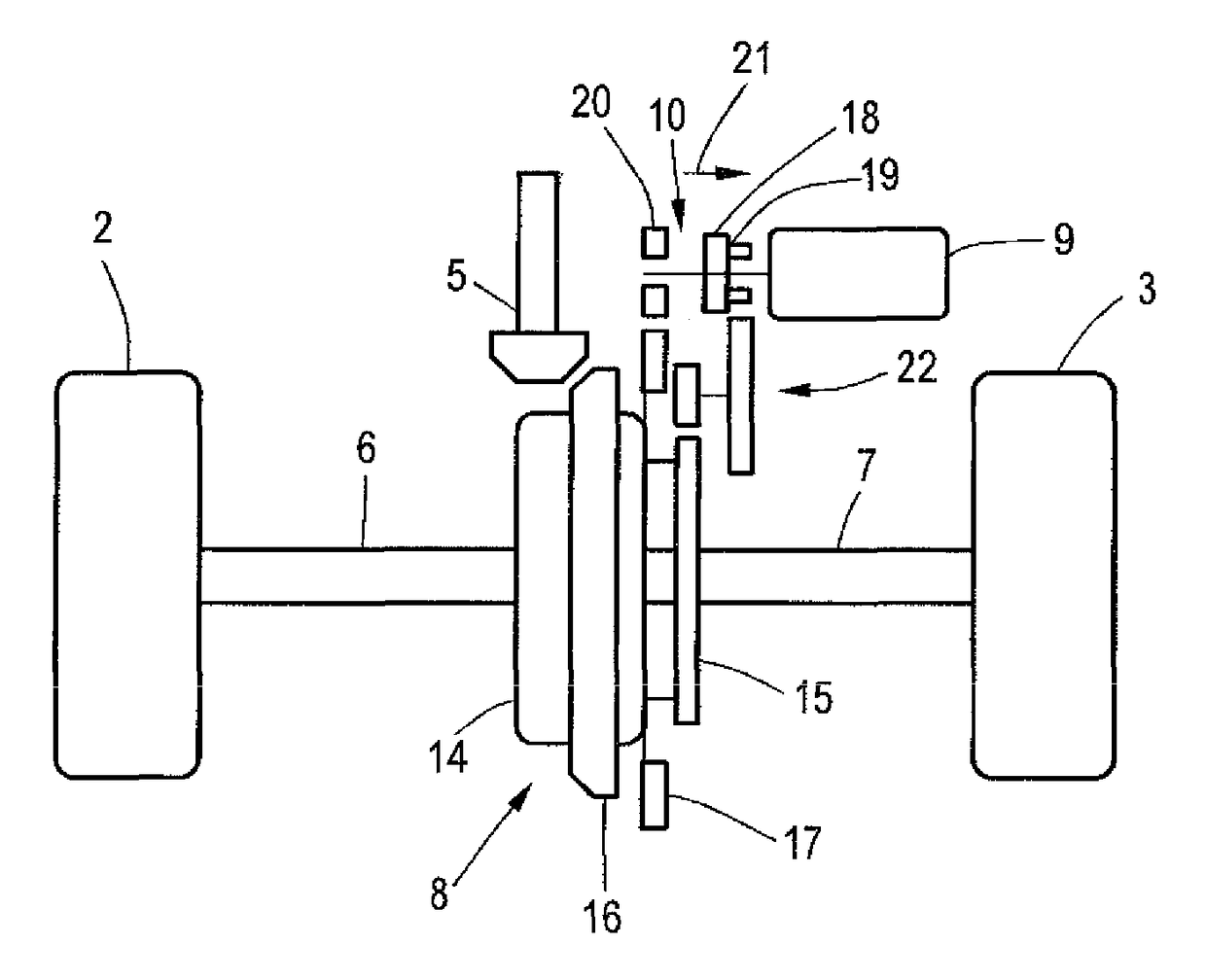
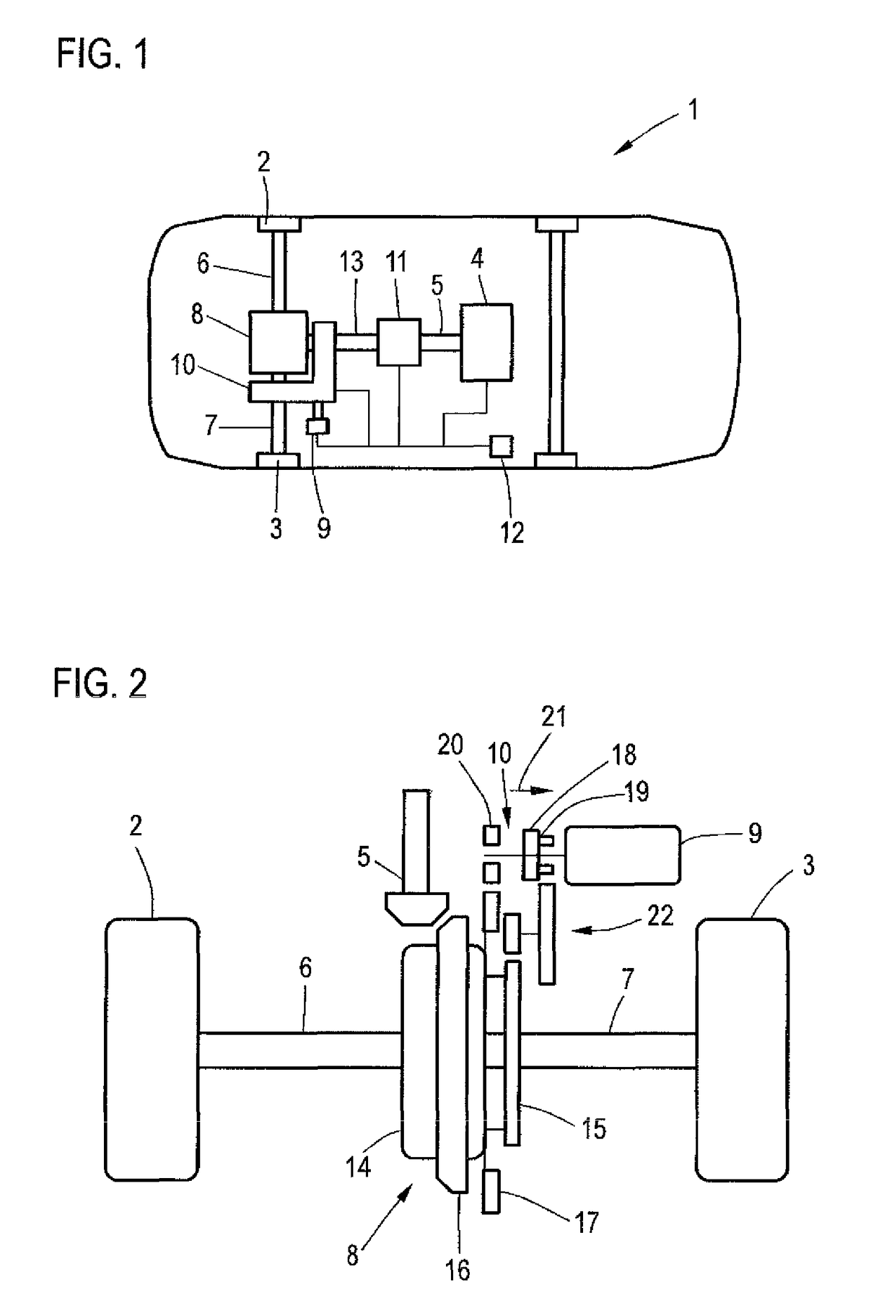
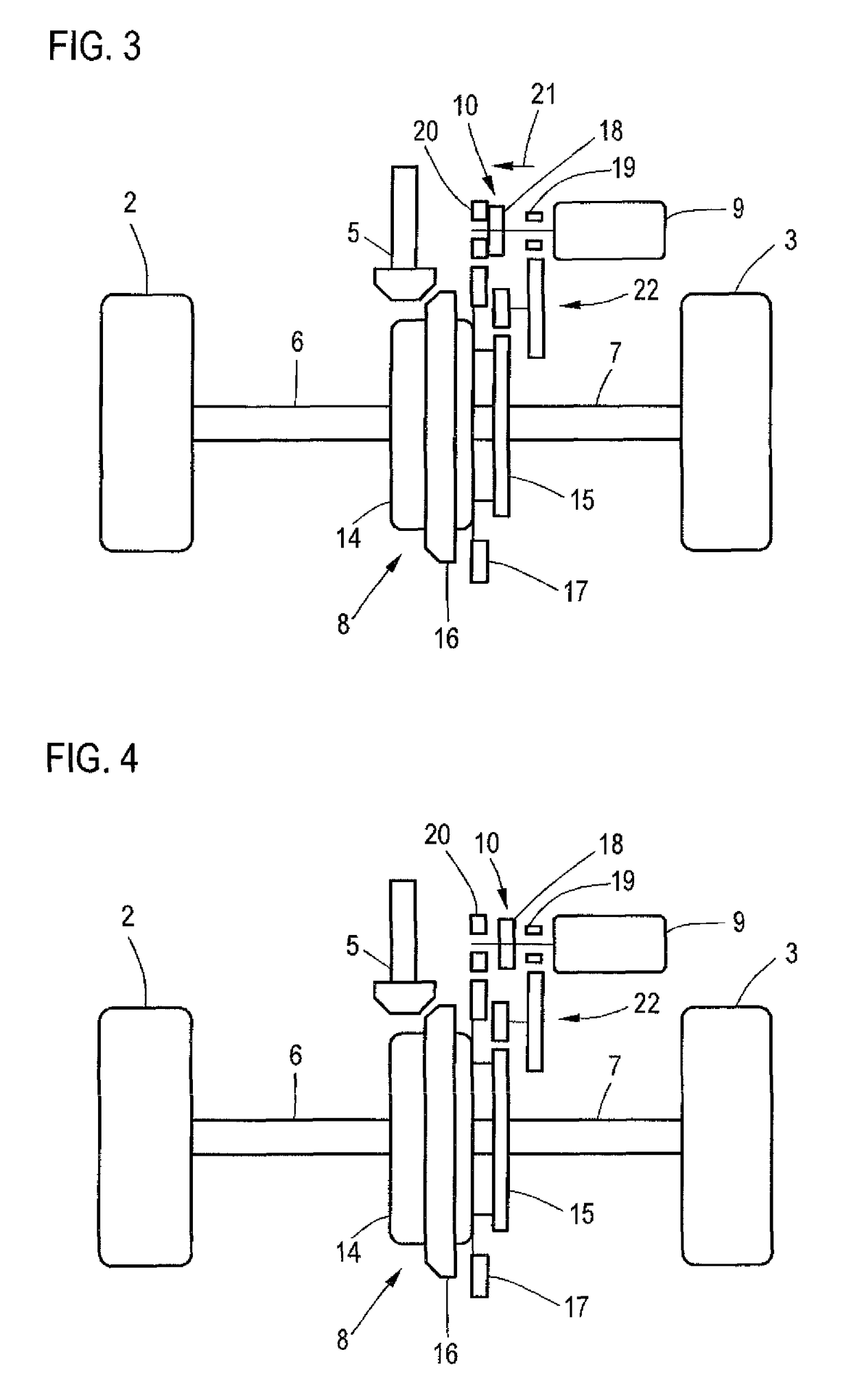
[0036]Throughout all the Figures, same or corresponding elements are generally indicated by same reference numerals. These depicted embodiments are to be understood as illustrative of the invention and not as limiting in any way. It should also be understood that the drawings are not necessarily to scale and that the embodiments are sometimes illustrated by graphic symbols, phantom lines, diagrammatic representations and fragmentary views. In certain instances, details which are not necessary for an understanding of the present invention or which render other details difficult to perceive may have been omitted.

[0037]Turning now to the drawing, and in particular to FIG. 1, there is shown a motor vehicle 1 with a left and a right rear wheel 2, 3, which are driven during normal driving operation by the drive motor 4, which is an internal combustion engine. The drive torque provided by the drive motor 4 via the drive shaft 5 is distributed between the rear wheels 2, 3 or between the out...


PUM


Abstract

A motor vehicle, includes a drive motor for driving the motor vehicle, at least one additional motor and at least one differential for distributing a torque generated by the drive motor and transmitted by a drive shaft to a driven differential element of the differential to two output shafts. The motor vehicle includes a coupling device which can be controlled by a control device, and in a first coupling state directly or indirectly couples the additional motor with an output shaft, thereby rendering the distribution of the drive torque to the output shafts dependent on an additional torque exerted by the additional motor, and in a second coupling state directly or indirectly couples the additional motor with the driven differential element.

Description

CROSS-REFERENCES TO RELATED APPLICATIONS[0001]This application claims the priority of German Patent Application, Serial No. 10 2014 007 940.6, filed May 24, 2015 pursuant to 35 U.S.C. 119(a)-(d), the disclosure of which is incorporated herein by reference.BACKGROUND OF THE INVENTION[0002]The invention relates to a motor vehicle including a drive motor for driving the motor vehicle, at least one additional motor and at least one differential for distributing a drive torque generated by the drive motor and transmitted to a driven differential element of the differential, to two output shafts.[0003]The following discussion of related art is provided to assist the reader in understanding the advantages of the invention, and is not to be construed as an admission that this related art is prior art to this invention.[0004]In order to improve the driving behavior of a motor vehicle it is known to use vehicle systems that distribute a torque provided by a drive motor between multiple axles ...

Claims


Application Information

Patent Timeline
Patent Type & Authority Patents(United States)
IPC IPC(8): B60K6/387B60K6/365F16H48/06B60K17/16F16H48/30F16H48/36B60K1/00
CPCB60K6/365B60K6/387B60K17/165F16H48/06F16H48/30B60K1/00B60K2001/001F16H2048/364Y10S903/902B60K6/48B60W10/02B60W10/08B60W10/16B60K2006/4808B60W2710/083B60W2720/406F16H48/10Y02T10/62
Inventor PINSCHMIDT, UDO
Owner AUDI AG
Why Eureka
Try Eureka