Optical module and camera module

a technology applied in the field of optical modules and camera modules, to achieve the effects of preventing friction loss, facilitating assembly, and smooth movemen

Inactive Publication Date: 2006-01-26
SEIKO INSTR INC
View PDF5 Cites 13 Cited by
  • Summary
  • Abstract
  • Description
  • Claims
  • Application Information

AI Technical Summary

Benefits of technology

[0012] Therefore, it is an object of the invention to provide an optical unit capable of being easily assembled, enabling its optical element to smoothly move, and preventing friction loss from being generated around its nut member.

Problems solved by technology

Also, the attachment accuracy of the driving unit does not contribute to the generation of the above-described deviation.

Method used


Image

  • Optical module and camera module
  • Optical module and camera module
  • Optical module and camera module

Examples


first embodiment

[0045] Hereinafter, the invention will be described with reference to FIGS. 1 to 3.

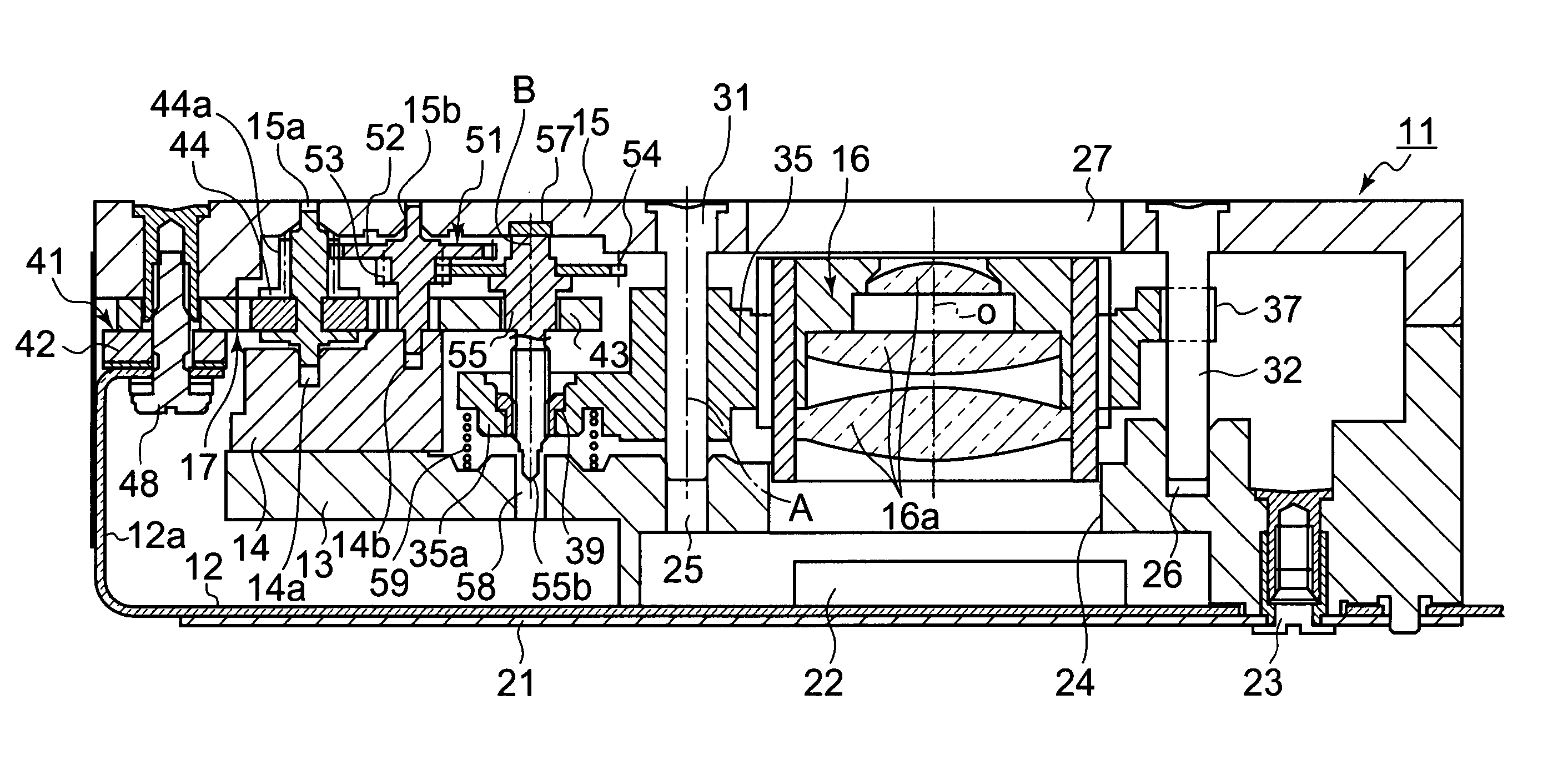
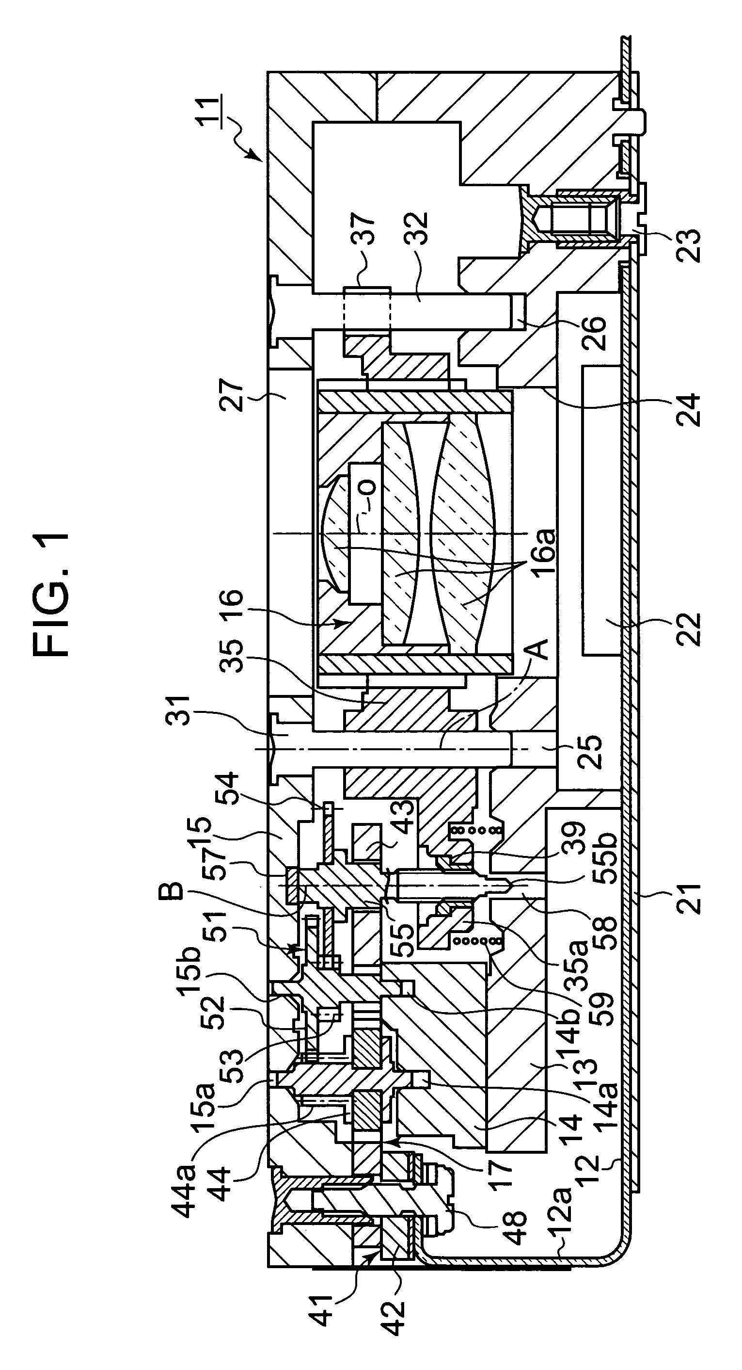
[0046] Referring to FIG. 1, an optical module, for example, a lens driving apparatus, designated by reference numeral 11 is mounted in a portable electronic appliance such as a card type digital camera or a camera-attached portable telephone. FIG. 1 is a cross-sectional view taken along a line F1-F1 in FIG. 3, illustrating the entire portion of the lens driving apparatus 11. The lens driving apparatus 11 includes a circuit board 12, a base member 13, a support block 14, a cover 15, an optical element, for example, a lens barrel 16, and a driving unit 17.

[0047] To the back surface of the circuit board 12, a support plate 21 harder than the circuit board 12 is attached in an insulated state. The circuit board 12 has one longitudinal end 12a bent to extend upwardly from the surface of the circuit board 12, and also to be substantially parallel with the support plate 21. An imaging element 22 such as a C...

third embodiment

[0088] In the third embodiment, in place of the protrusions 39bb formed at the nut 39, an elongated protrusion 39b may be formed which is protruded from the fixing member, namely, the yoke 43, toward the nut 39, or protrusions 39b may be formed which are protruded from both the yoke 43 and the nut 39, in order to limit the maximal movement amount of the holder 35 and to prevent separation of the nut 39 when the lead screw 55 rotates excessively.

[0089]FIG. 7 illustrates a fourth embodiment of the invention. Basically, this embodiment is identical to the first embodiment. Accordingly, elements of the fourth embodiment identical to those of the first embodiment are designated by the same reference numerals, respectively, and no description thereof will be given. The fourth embodiment is different from the first embodiment in that the fourth embodiment includes a configuration capable of supporting the lead screw 55 in a radial direction as well while allowing a predetermined inclined m...

seventh embodiment

[0104]FIG. 10 illustrates the invention. This embodiment is a use example in which the optical module of the invention is applied to an electronic appliance. Also, elements of the embodiment identical to those of the above-described embodiments are designated by the same reference numerals, respectively, and no description thereof will be given.

[0105] The optical module 11 may be incorporated in a camera module 100 which is mounted in a camera. The camera module 100 may includes, for example, the optical module 11, the imaging element 22, and a circuit block 101. The imaging element 22 converts an image subjected to focus adjustment or zooming through a lens, which is the optical element 16 of the optical module 11, into an electronic signal. The circuit block 101 includes a controller 111, a motor driver 105, and a signal processor 113. The controller 111 includes a CPU, a memory, and the like. The controller 111 performs control for the entire portion of the camera module 100 incl...


PUM


Abstract

An optical unit is disclosed which is capable of being easily assembled, enabling its optical element to smoothly move, and preventing friction loss from being generated around its nut member. A lens driving apparatus is provided for moving an optical element holder, which supports an optical element having an optical axis and is movable along a guide member, in an extension direction of the optical axis, using a nut integrally provided at the holder, and a lead screw threadedly coupled to the nut to rotate forward and backward by a driving unit. In the lens driving apparatus, the forward or backward rotation of the motor is transmitted to the lead screw via a reduction gear train. The lead screw is installed to be inclinedly movable with respect to the extension direction of the optical axis about threaded coupling portions of a threaded section of the lead screw and the nut.

Description

BACKGROUND OF THE INVENTION [0001] 1. Field of the Invention [0002] The present invention relates to an optical module which is mounted in a portable electronic appliance such as a card type digital camera or a camera-attached telephone, and is equipped with an optical element movable for focus adjustment, zooming, or the like, and a camera module using the same. [0003] 2. Description of the Related Art [0004] Japanese Patent Publication No. 3031127 discloses a lens driving apparatus for moving a lens in an extension direction of an optical axis (hereinafter, referred to as an “optical axis direction”). As disclosed in Japanese Patent Publication No. 3031127 (Para. 0007-0009, and FIGS. 1 to 3), this lens driving apparatus includes a motor provided with a lead screw as a rotating shaft thereof, a lens holding frame slidable along a guide shaft extending in the optical axis direction, and a nut mounted to the lens holding frame such that the nut is substantially integrated with the le...

Claims


Application Information

Patent Timeline
Patent Type & Authority Applications(United States)
IPC IPC(8): F16H27/02
CPCG02B7/102Y10T74/18576H04N5/2254H04N23/55
Inventor HASEGAWA, HARUHIKOKITAJIMA, HIDEKIMASUDA, SHIGEYUKINOMURA, TAMIOKOSAKA, TAKAYUKI
Owner SEIKO INSTR INC
Why Eureka
Try Eureka