Handheld extruder welding device

a welding device and extruder technology, which is applied in the field of hand-held extruder welding devices, can solve the problems of plastic welding wire twisting and difficult handling, and achieve the effects of increasing the penetration depth of plastic welding wire, cost-efficient manufacturing, and easy inserting

Active Publication Date: 2006-03-16
LEISTER TECHNOLOGIES
View PDF4 Cites 12 Cited by
  • Summary
  • Abstract
  • Description
  • Claims
  • Application Information

AI Technical Summary

Benefits of technology

[0007] According to the invention, in its feed channel, the handheld extruder welding device has a ridge running in longitudinal direction that presses into the plastic welding wire, holding it in position with the result that it is not twisted to any significant degree by the rotation of the extrusion screw. This has the effect that the plastic welding wire protruding from the handheld extruder welding device is positively prevented from twisting, as desired. In principle, this ridge may be designed with edges or as a round element. Preferably, the ridge is sharp in order to avoid friction loss, on the one hand, and in order to engage the plastic welding wire to the greatest possible extent for the purpose of positive guidance.
[0009] In accordance with a preferred design, the bottom of the feed channel runs at an angle to the extrusion screw so that the depth of the feed channel decreases continuously, tapering off at the end. This has the effect of continuously increasing the penetration depth of the plastic welding wire into the feed zone of the handheld extruder welding device during the feeding process.
[0010] Depending on the production process, the feed channel may be located in a one- or two-piece sleeve surrounding the extrusion screw. This offers considerable advantages for the manufacture and assembly of the handheld extruder welding device because the sleeve can be made separately and is easy to insert. In a one piece sleeve, the feed channel can be made by means of wire erosion, and by means of a cutting process in a two-piece sleeve. Sintering processes are also suitable for this.
[0011] In accordance with a special design of the handheld extruder welding device, the sleeve is held in a holding element of the housing with a central passage for the extrusion screw, surrounding the extrusion screw in the feed zone. Holding the feeding sleeve in position in this manner offers enormous advantages in terms of cost-efficient manufacture as well as a high degree of stability. Depending on the design of the handheld extruder welding device, the holding element may serve simultaneously as a cooling body carrying a housing in which, in contrast to the state of technology, the drive system as well as parts of the heating device are integrated. In addition, the holding element / cooling body may also serve for clamping the gear output for the extrusion screw. It is also possible to use the holding element only as a separating element for the gear output of a handheld extruder welding device. Thus, the arrangement of the feed channel in such a design permits various designs of handheld extruder welding devices without a change of the sleeve.

Problems solved by technology

In all known handheld extruder welding devices, twisting of the plastic welding wire is a problem because, due to the rotation of the extrusion screw, the plastic welding wire is twisted around its longitudinal axis, in addition to its previous twisting caused by its unwinding from a spool device.
This causes undesirable loops and twists that make it harder to handle and may require an interruption of the welding process in order to eliminate the loops.

Method used


Image

  • Handheld extruder welding device
  • Handheld extruder welding device
  • Handheld extruder welding device

Examples


Embodiment Construction

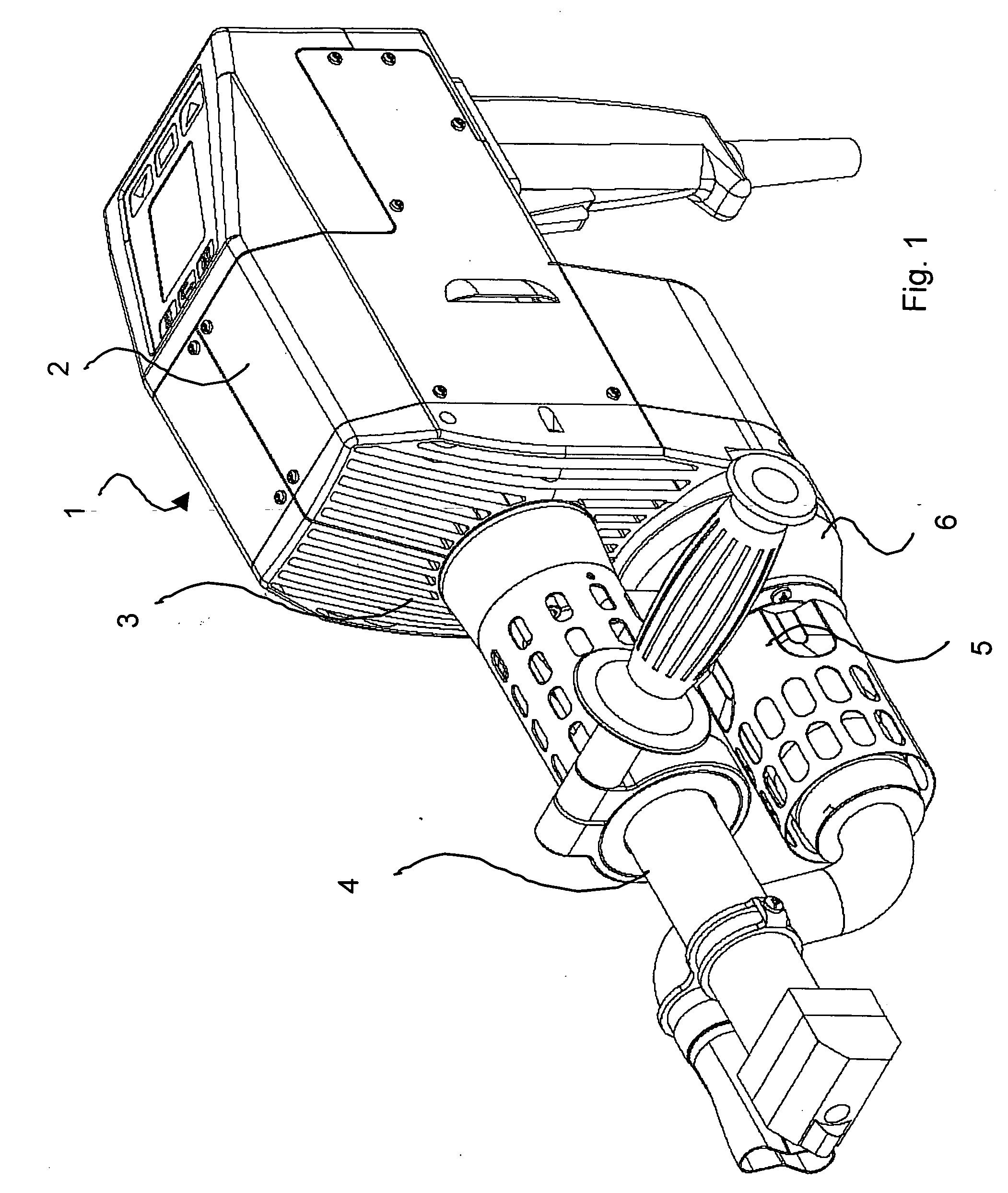
[0021]FIG. 1 shows a design variant of a handheld extruder welding device 1 with a housing 2 having a cooling body 3 as base component and bearing element.

[0022] On the other side of the cooling body 3, a screw cylinder 4 contains an extrusion screw 8 and a heating device 5 preceded by a blower 6. The extrusion screw 8 has a feed zone 11 (FIG. 3) and a conveying / plasticizing zone.

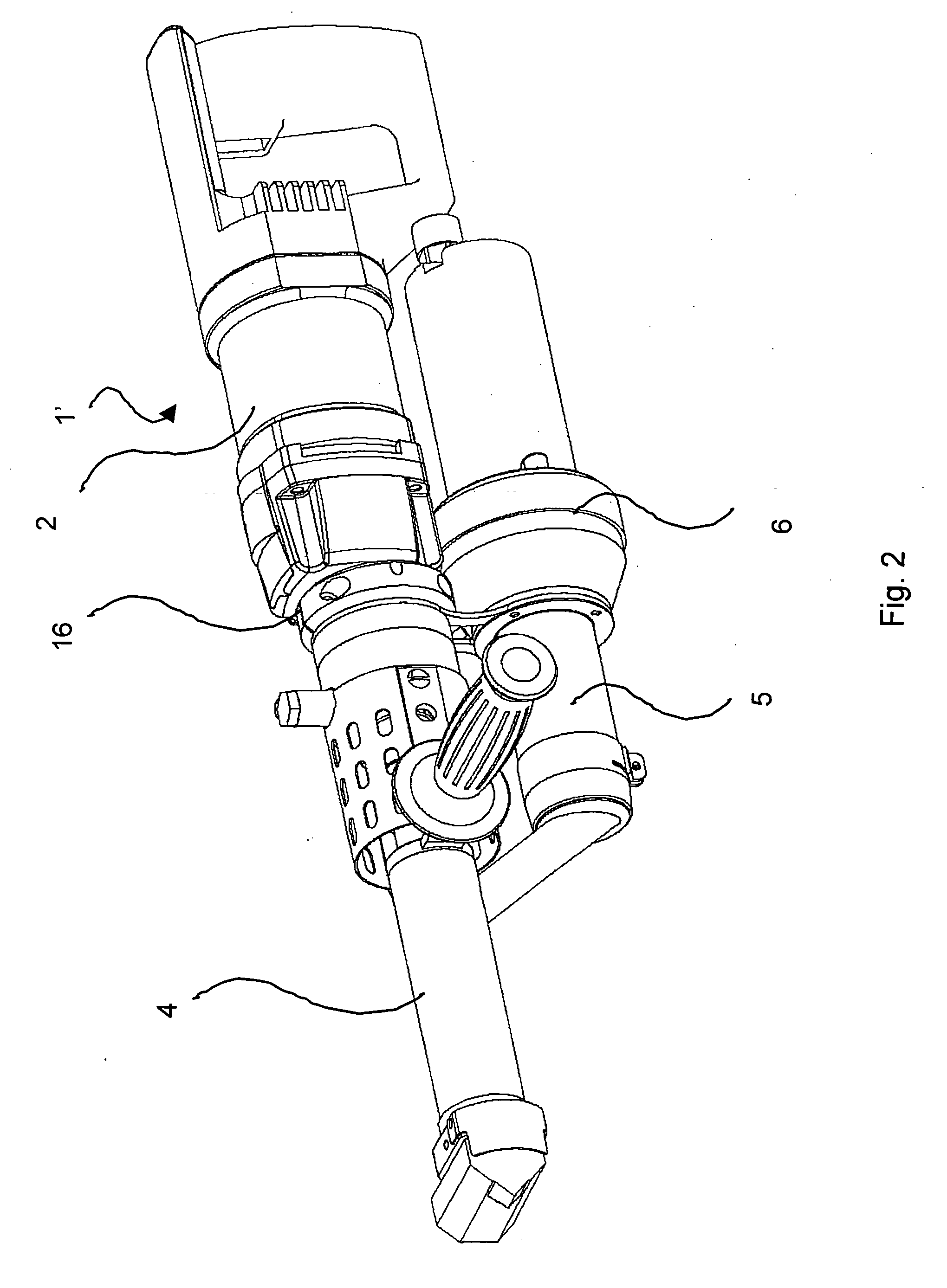
[0023]FIG. 2 shows a different design of a handheld extruder welding device 1′ where the heating device 5 preceded by the blower 6 is not integrated in the housing 2, and therefore does not have a cooling body 3 as shown in FIG. 1.

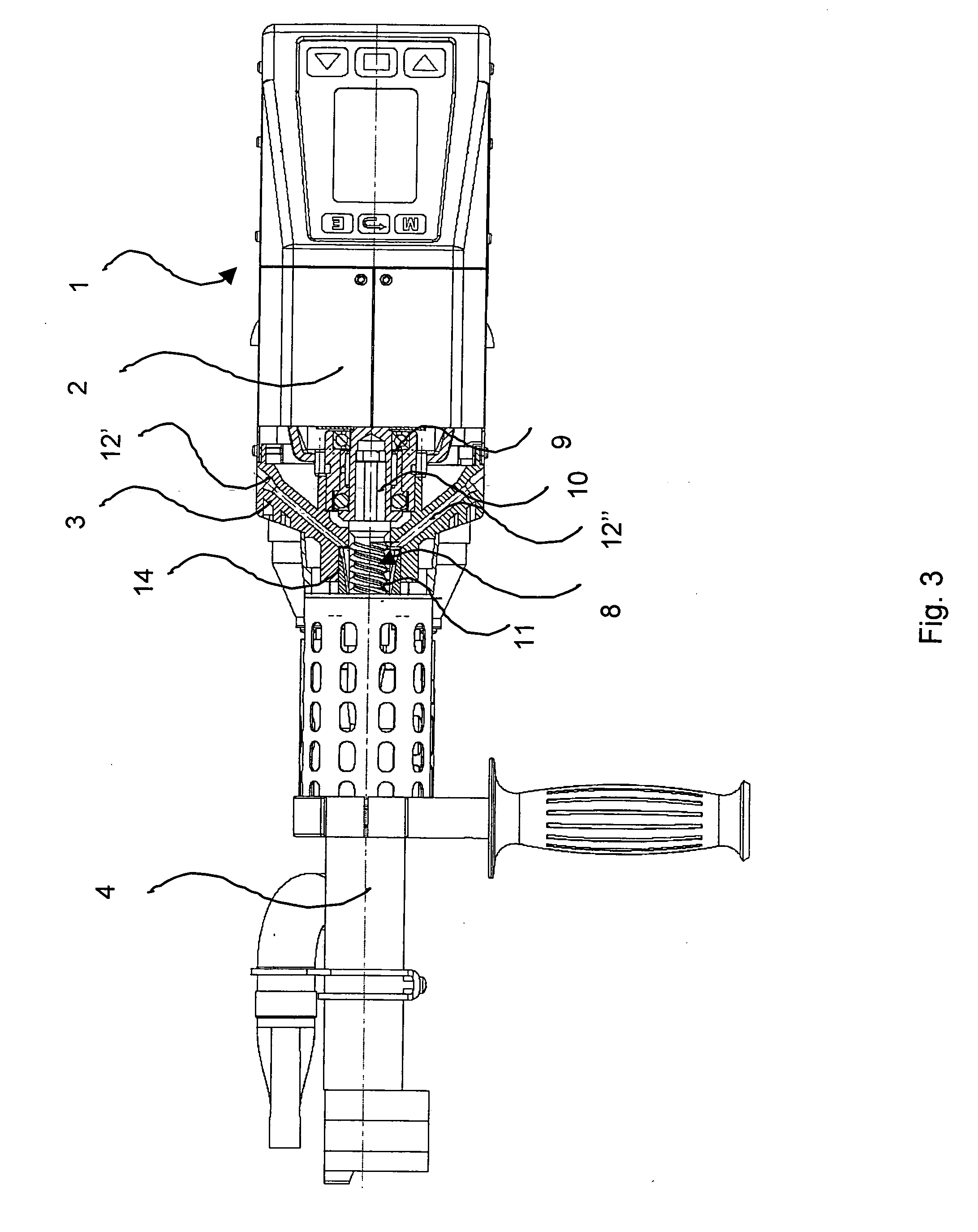
[0024] In a partial section of the handheld extruder welding device 1 according to FIG. 1, FIG. 3 shows part of the extrusion screw 8 with the shaft 10 inserted in the bearing 9, and the feed zone 11 that follows it.

[0025] The enlarged view in FIG. 4 shows two different supply channels 12′ and 12″ in the cooling body 3 for welding wires of different diameters that each end in ...


PUM

PropertyMeasurementUnit
heightaaaaaaaaaa
heightaaaaaaaaaa
lengthaaaaaaaaaa

Abstract

A handheld extruder welding device is provided for welding thermoplastic synthetic materials by means of an extrusion screw with a feed zone and a conveying / plasticizing zone. In the area of the feed zone, a feed channel with a ridge running in longitudinal direction is located in a sleeve. This ridge prevents the inserted plastic welding wire from twisting and looping inside and especially outside the handheld extruder welding device.

Description

TECHNICAL FIELD [0001] This invention concerns a handheld extruder welding device for welding thermoplastic synthetic materials by means of an extrusion screw driven by a drive system enclosed in a housing, a screw cylinder surrounding the extrusion screw, and at least one feed channel for the plastic welding wire that extends, at least partially, over the length of the feed zone of the extrusion screw and has the shape of a chute. BACKGROUND OF THE INVENTION [0002] Handheld extruder welding devices are familiar devices, and are used primarily for welding plastic panels or similar objects. Such devices consist essentially of a handheld drill serving as the drive system and a removable attachment for this drill. In the attachment, a strand of plastic in the shape of a plastic wire that is supplied via a feed channel and a feed device is first chopped up, and is then plasticized by means of a screw and a heating device. A welding device of this type is known from DE-A-28 23 171, for e...

Claims


Application Information

Patent Timeline
Patent Type & Authority Applications(United States)
IPC IPC(8): A47J36/02B29C48/02B29C48/06B29C48/25B29C48/395
CPCB29C47/0002B29C47/0016B29C47/08B29C66/861B29C65/40B29C66/0242B29C47/38B29C66/73921B29C48/02B29C48/06B29C48/25B29C48/395
Inventor DI MICELI, GUISEPPEARNOLD, HANS
Owner LEISTER TECHNOLOGIES
Why Eureka
Try Eureka