Motor device and wiper apparatus

a technology of motor devices and wipers, which is applied in the direction of vehicle maintenance, vehicle cleaning, gearing, etc., can solve the problems of lack of torque of wiper motors, poor wiping effect, and poor positioning accuracy of wipers

Inactive Publication Date: 2012-08-07
ASMO CO LTD
View PDF46 Cites 2 Cited by
  • Summary
  • Abstract
  • Description
  • Claims
  • Application Information

AI Technical Summary

Benefits of technology

[0006]An objective of the present invention is to provide a wiper motor which can be downsized.

Problems solved by technology

In the case that the link mechanism is not provided, and an output shaft of the wiper motor is directly connected to the wiper to reciprocate the wiper, a positional accuracy of the wiper may deteriorate in the case that the wiper is positioned at an upper reverse position and in the case that the wiper is positioned at a lower reverse position.
That is, the lack of torque of the wiper motor may be generated near the lower reverse position and the upper reverse position, where a relatively great wiping force is needed to operate the wiper.
There is a tendency that a mounting space of the wiper apparatus to a vehicle is limited more and more.

Method used


Image

  • Motor device and wiper apparatus
  • Motor device and wiper apparatus
  • Motor device and wiper apparatus

Examples


first embodiment

[0021]FIGS. 1 to 4 show a wiper apparatus in accordance with the present invention.

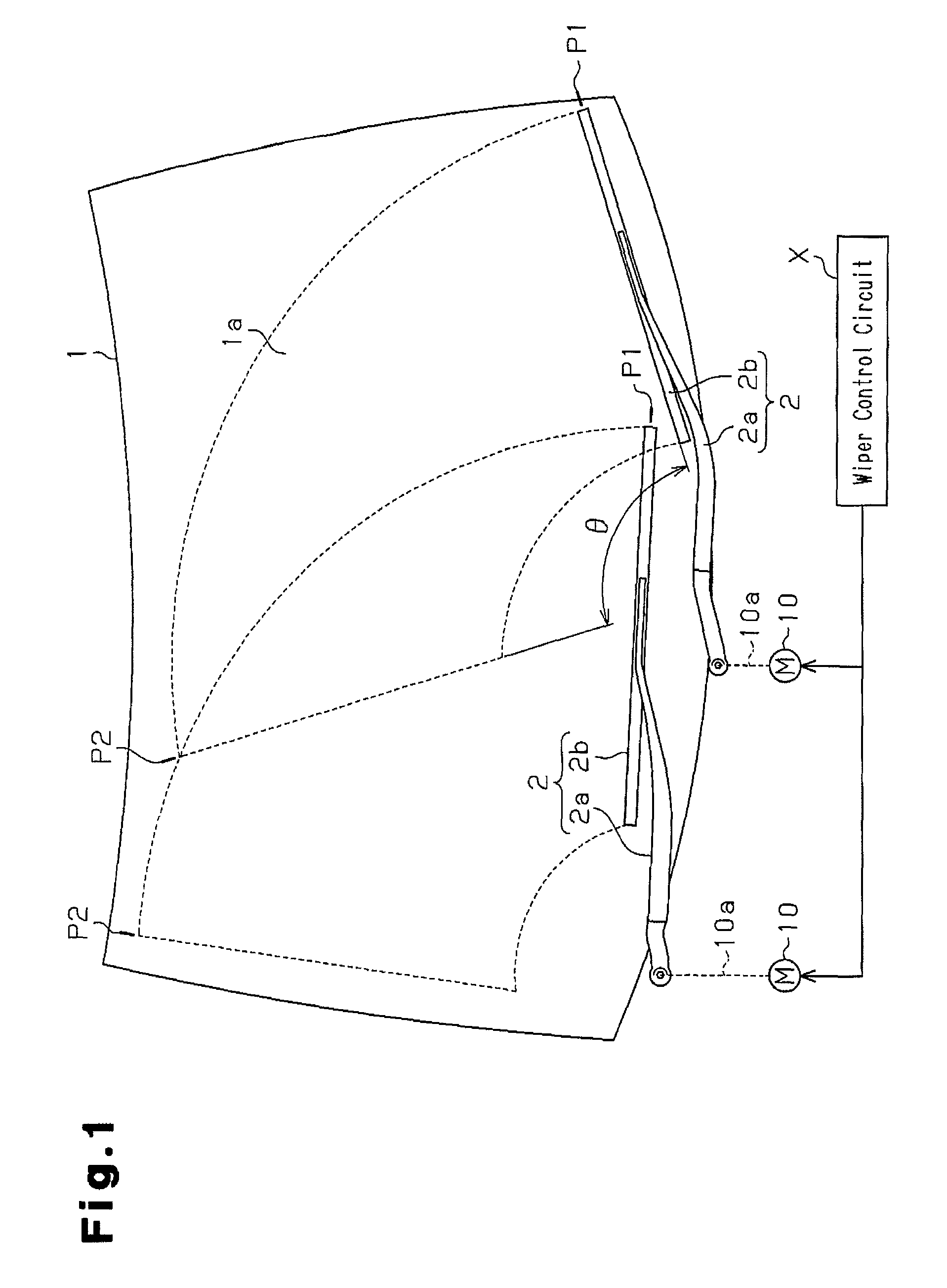
[0022]As shown in FIG. 1, the wiper apparatus is provided with a pair of wipers 2, a pair of wiper motors 10, and a wiper control circuit X. The wiper control circuit X synchronously controls both wiper motors 10. The wiper motors 10 each serving as a motor device respectively reciprocate and rotate the wipers 2. Each of the wipers 2 wipes rainwater or the like on a glass surface 1a corresponding to a surface-to-be-wiped of a vehicle front glass 1. Each of the wipers 2 is swung in a reciprocating manner between a lower reverse position P1 and an upper reverse position P2. The wiper 2 positioned at the lower reverse position P1 extends in a lateral direction of the vehicle, and the wiper 2 positioned at the upper reverse position P2 extends in a vertical direction. Since each of the lower reverse positions P1 also serves as a stop position of the wiper 2, it can be expressed by “stop / lower reverse posi...


PUM


Abstract

A sectoral reduction gear is arranged between a motor portion and a link mechanism. The sectoral reduction gear rotates in a reciprocating manner in a predetermined angle range on the basis of a forward rotation and a reverse rotation of the motor portion. An outer periphery of the sectoral reduction gear defines an imaginary circle. An inner region of the imaginary circle has an operating range in which the sectoral reduction gear, which rotates in a reciprocating manner, passes, and a non-operating range, in which the sectoral reduction gear does not pass. As seen from an axial direction of an output shaft, a part or the whole of the output shaft is arranged in the non-operating range.

Description

BACKGROUND OF THE INVENTION[0001]The present invention relates to a motor device and a wiper apparatus. The motor device is provided with a motor portion which can be rotated forward and in reverse, and a link mechanism coupled drivingly to the motor portion. The link mechanism is integrally assembled in the motor portion. The wiper apparatus is provided with the motor device and a wiper control circuit controlling the motor device.[0002]A motor device disclosed in Japanese Laid-Open Patent Publication No. 11-34805 is used as a wiper motor reciprocating a vehicle wiper. A link mechanism compensate for a lack of torque.[0003]In the case that the link mechanism is not provided, and an output shaft of the wiper motor is directly connected to the wiper to reciprocate the wiper, a positional accuracy of the wiper may deteriorate in the case that the wiper is positioned at an upper reverse position and in the case that the wiper is positioned at a lower reverse position. This is because t...

Claims


Application Information

Patent Timeline
Patent Type & Authority Patents(United States)
IPC IPC(8): B60S1/24
CPCB60S1/166B60S1/245Y10T74/1563Y10T74/19828Y10T74/1569
Inventor MATSUMOTO, HIROSHIYAMANISHI, MASAHIKO
Owner ASMO CO LTD
Why Eureka
Try Eureka