
Continuously variable transmission

a technology of transmission and drive shaft, applied in the direction of friction gearing, gearing elements, gearing, etc., can solve the problems of power transmission not being transmitted, gear ratios cannot be assured during normal rotation, and not matching each other

Inactive Publication Date: 2015-12-03
TOYOTA JIDOSHA KK
View PDF0 Cites 56 Cited by
  • Summary
  • Abstract
  • Description
  • Claims
  • Application Information

AI Technical Summary

Benefits of technology

The invention provides a solution for problems in conventional technology by providing a continuously variable transmission. The transmission includes three power transmission components that rotate around a common axis. A rolling component is positioned between the first and second power transmission components, with a support shaft and guide members for each component. The guide members ensure that forces between the components match during rotation. A gear shift member is provided for changing gear ratios, and an actuator controls the movement of the rolling components. The invention addresses issues in conventional technology and improves the performance and efficiency of the transmission.

Problems solved by technology

Therefore, a skew generated by a deviation of the rotation axes of the rolling components is not generated because of the two fixed plates, and a gear ratio cannot be assured during normal rotation.
However, if the fixed plate is made rotatable, when the rotation directions of the first and second power transmission components are reversed, the forces applied therebetween do not match each other.
That is, there is a possibility that the power may not be transmitted or the gear ratio may not be changed after the transmission of the power during the reverse rotation of the first and second power transmission components.

Method used


Image

  • Continuously variable transmission
  • Continuously variable transmission
  • Continuously variable transmission

Examples


Embodiment Construction

[0023]Hereinafter, an embodiment of a continuously variable transmission according to the invention will be described with reference to the drawings. Furthermore, the invention is not limited to the embodiment.

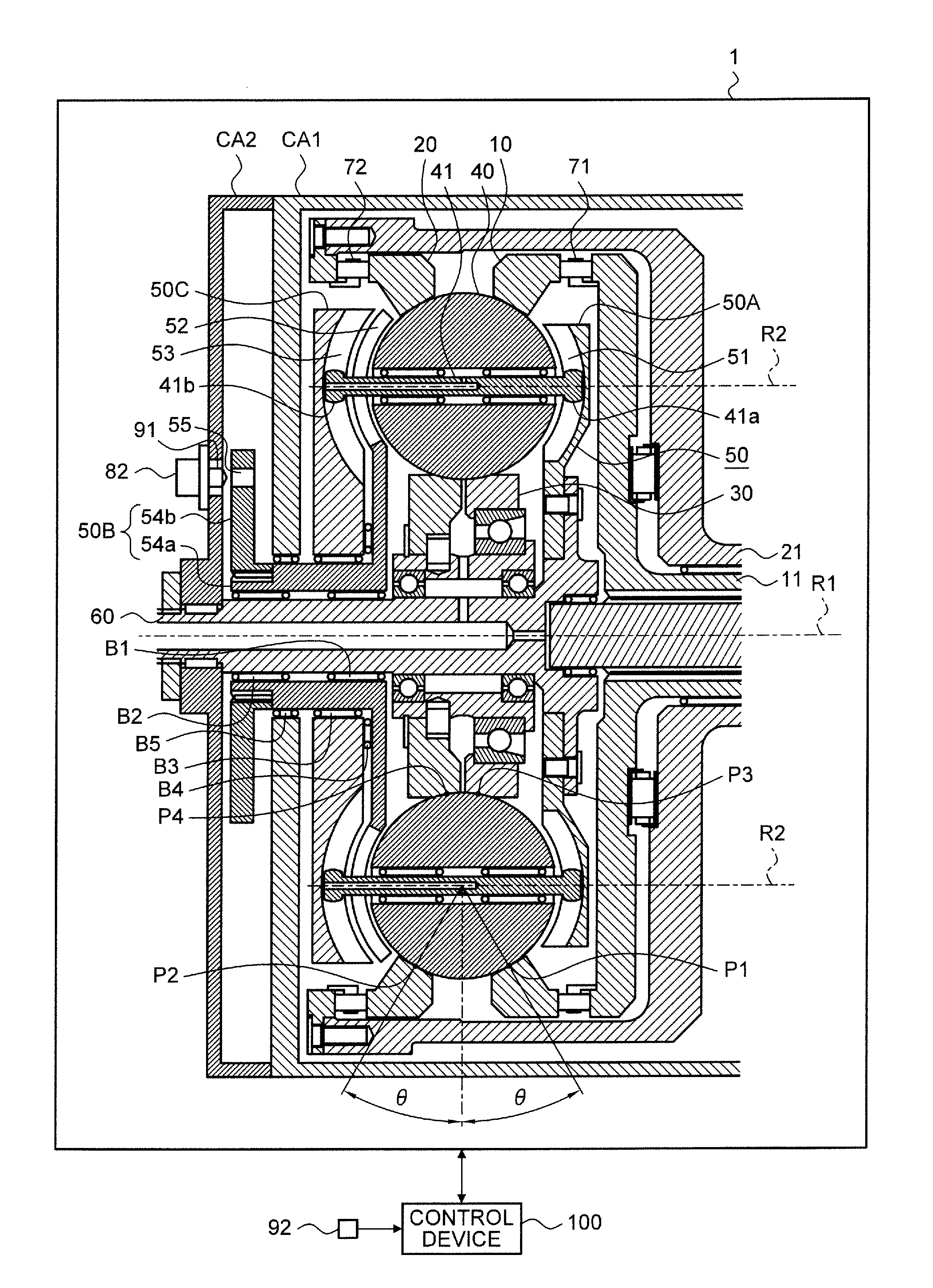
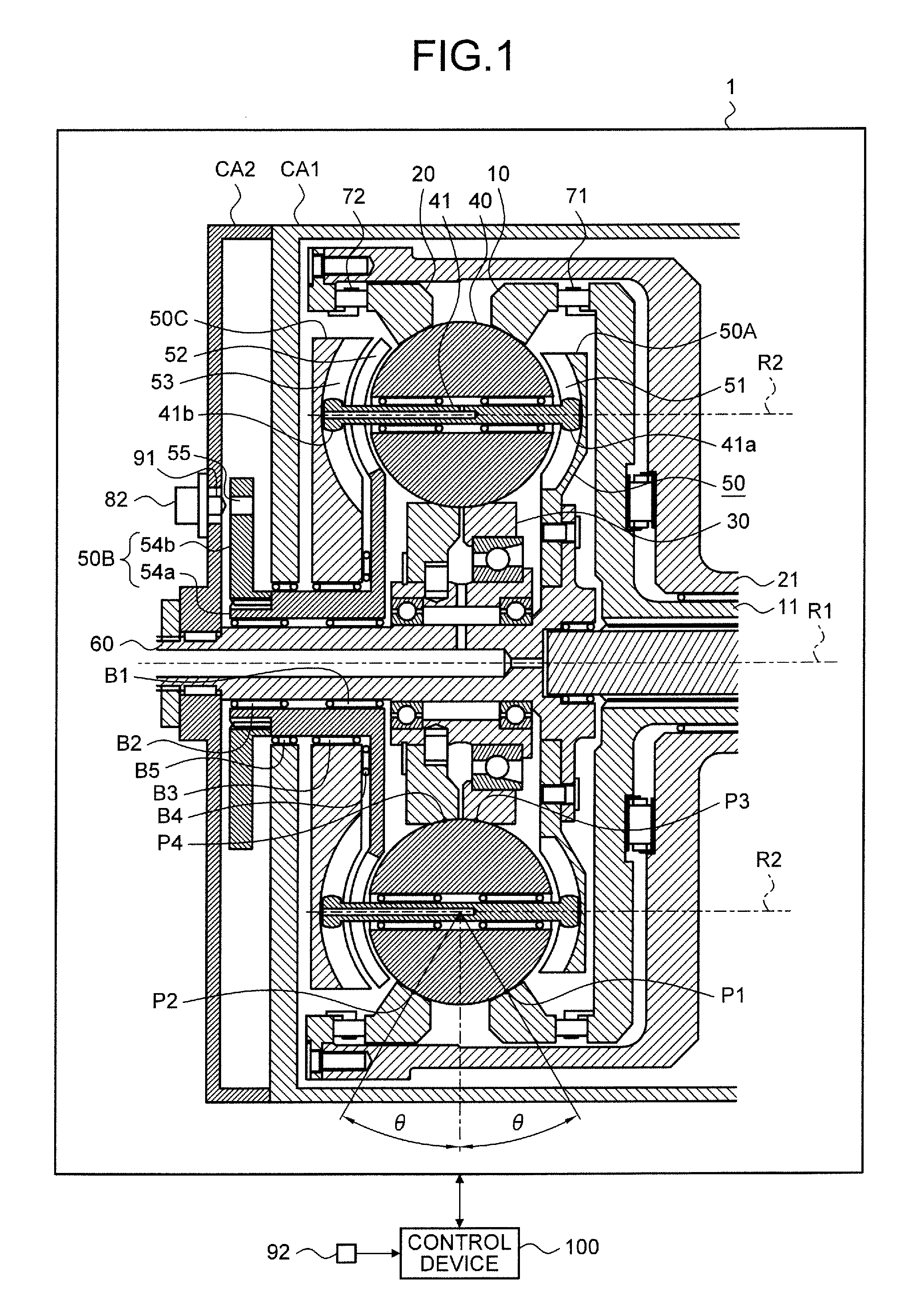
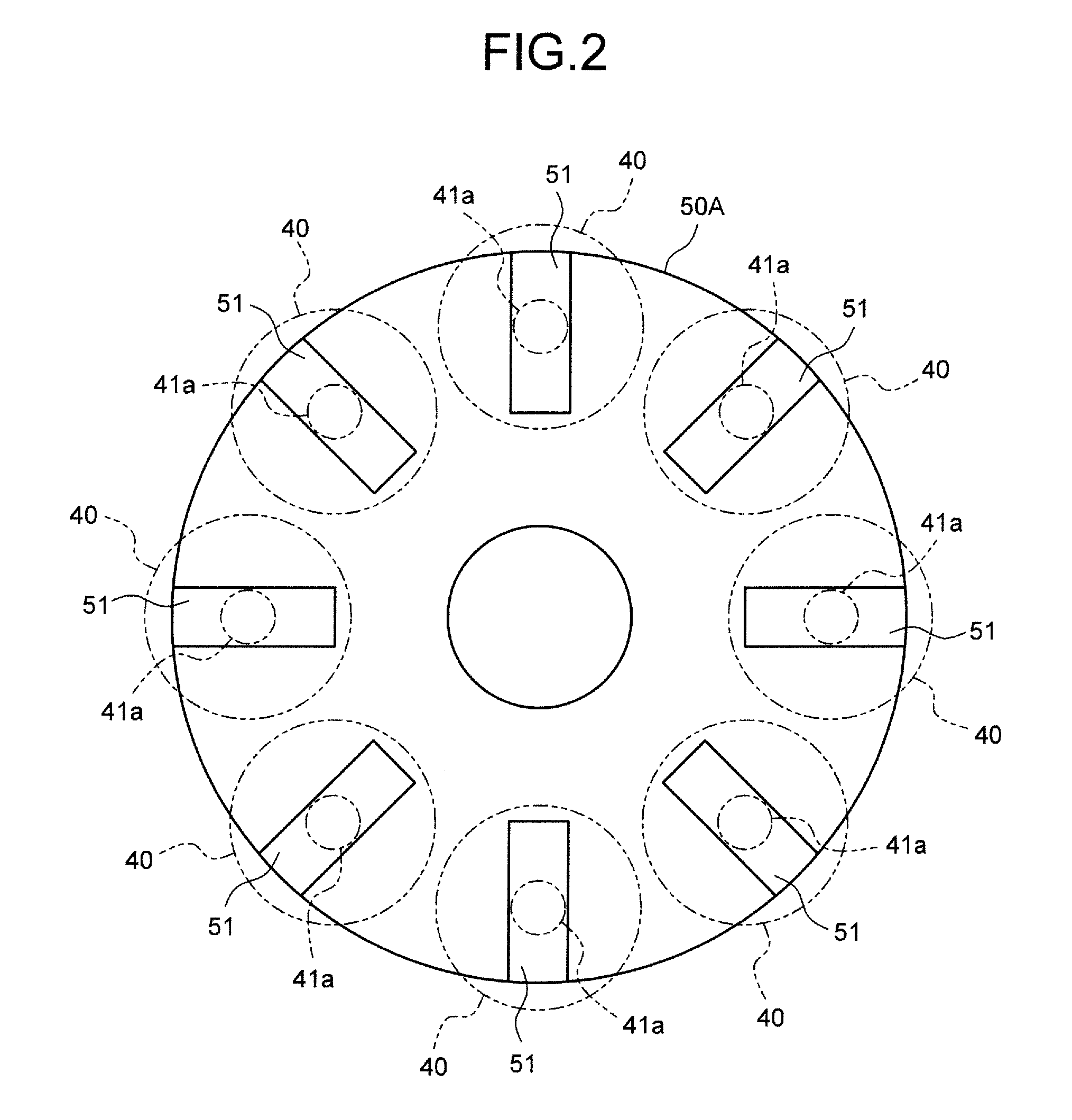
[0024]An embodiment of a continuously variable transmission according to an embodiment of the invention will be described with reference to FIGS. 1 to 13.

[0025]The continuously variable transmission in the embodiment is a so-called traction drive type continuously variable transmission, and a ball planetary type continuously variable transmission will be representatively exemplified.

[0026]The continuously variable transmission includes first to third power transmission components, rolling components, and holding components. The first to third power transmission components include a first rotation axis R1 which is commonly set therebetween, and hence are relatively rotatable in the circumferential direction with respect to the first rotation axis R1. Each of the rolling compone...


PUM


Abstract

A continuously variable transmission includes: first to third power transmission components; a rolling component; a support shaft for the rolling component; a first guide member that includes a first guide portion for guiding a first protrusion portion of the inserted support shaft; a gear shift member that includes a gear change portion; a first actuator which tilts each rolling component by moving each second protrusion portion along the gear change portion with rotation of the gear shift member at a time an input-output gear ratio is changed; a second guide member that includes a second guide portion for guiding a second protrusion portion of the inserted support shaft; and a second actuator which prohibits rotation of the second guide member during reverse rotation of the first and second power transmission components and allows rotation of the second guide member during normal rotation of the first and second power transmission components.

Description

CROSS-REFERENCE TO RELATED APPLICATION(S)[0001]The present application claims priority to and incorporates by reference the entire contents of Japanese Patent Application No. 2014-113358 filed in Japan on May 30, 2014.BACKGROUND OF THE INVENTION[0002]1. Field of the Invention[0003]The present invention relates to a traction drive type continuously variable transmission that continuously changes an input-output gear ratio.[0004]2. Description of the Related Art[0005]Conventionally, for example, a ball planetary type continuously variable transmission disclosed in Japanese National Publication of International Patent Application No. 2012-506001 and Japanese Patent Application Laid-open No. 2012-225390 is known. The continuously variable transmission includes three power transmission components (two disks or two rings and a sun roller) which have a common rotation axis, rolling components (planet balls) which are radially disposed with respect to the rotation axis and are sandwiched by...

Claims


Application Information

Patent Timeline
IPC IPC(8): F16H15/52F16H63/08
CPCF16H63/08F16H15/52F16H15/28
Inventor OGAWA, HIROYUKI
Owner TOYOTA JIDOSHA KK
Learn More