Transport apparatus

a technology of transport apparatus and rail, which is applied in the direction of programmed manipulators, manufacturing tools, transportation and packaging, etc., can solve the problems of limited upward movable range, longitudinal or lateral movement, and rotation of the arm, so as to improve the balance of the transport apparatus and facilitate the extension or shortening of the rail.

Active Publication Date: 2005-09-08
LINE WORKS CO LTD
View PDF18 Cites 54 Cited by
  • Summary
  • Abstract
  • Description
  • Claims
  • Application Information

AI Technical Summary

Benefits of technology

[0012] Further, in the present invention, revolving wheel bearings are used in the column rotation mechanism, the head rotation mechanism, and the jig mounting stage rotation mechanism, and motors and reduction gears are used in the column rotation mechanism drive source, the head rotation mechanism drive source, and the jig mounting stage rotation mechanism drive source for driving the revolving wheel bearings. In this case, the head rotation mechanism drive source and the jig mounting stage rotation mechanism drive source are arranged at the rear of the rev

Problems solved by technology

While it is of an articulated six-axis type, a conventional handling robot has a main body that is stationary, which means it is incapable of moving longitudinally or laterally; its arm, which rotates, has its limitations in rotation range.
Further, while the robot arm is capable of vertical rotation, the robot main body does not extend upwardly, so that there are limitations regarding the upward movable range.
Thus, the conventional handli

Method used


Image

  • Transport apparatus
  • Transport apparatus
  • Transport apparatus

Examples


embodiment 1

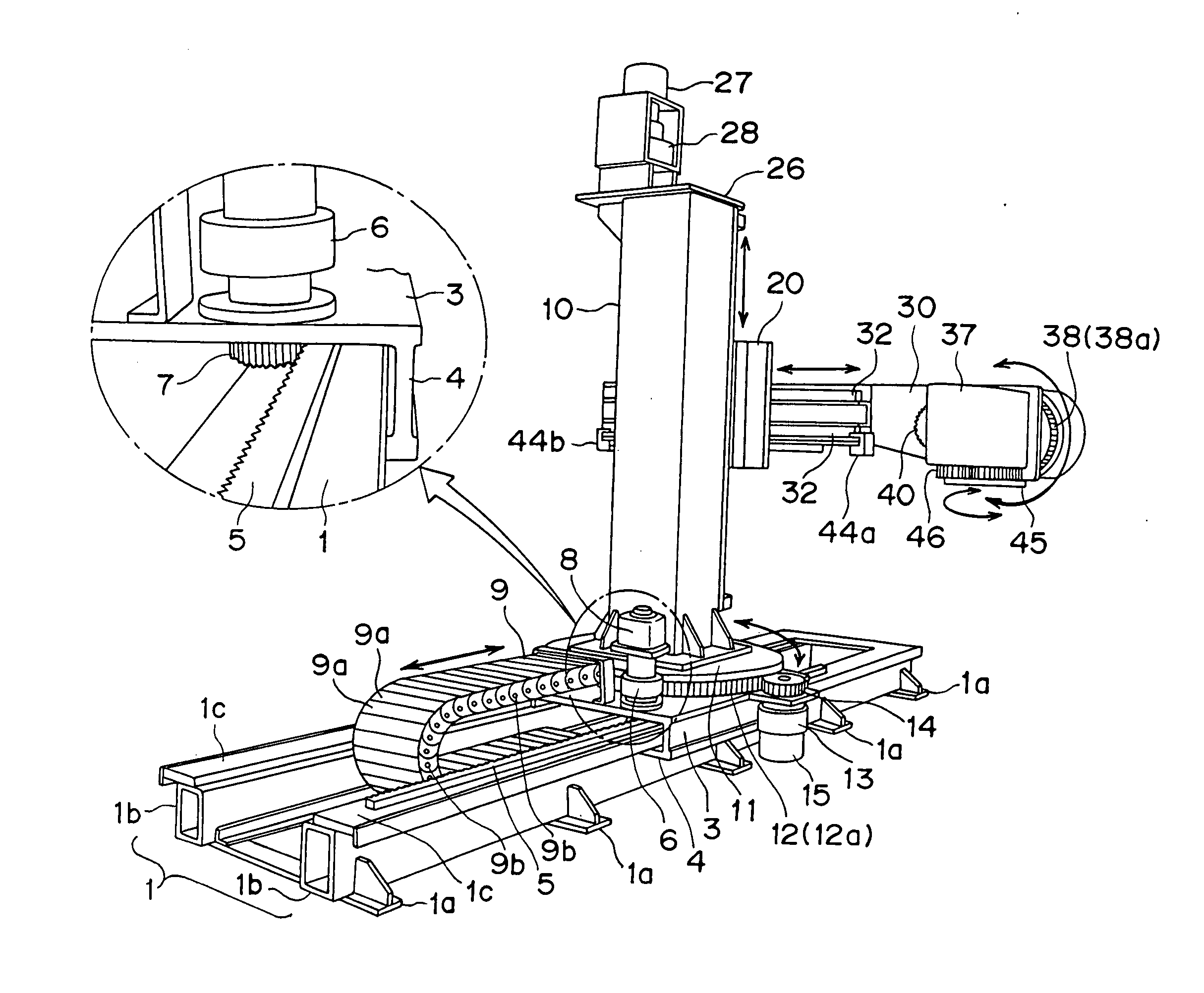
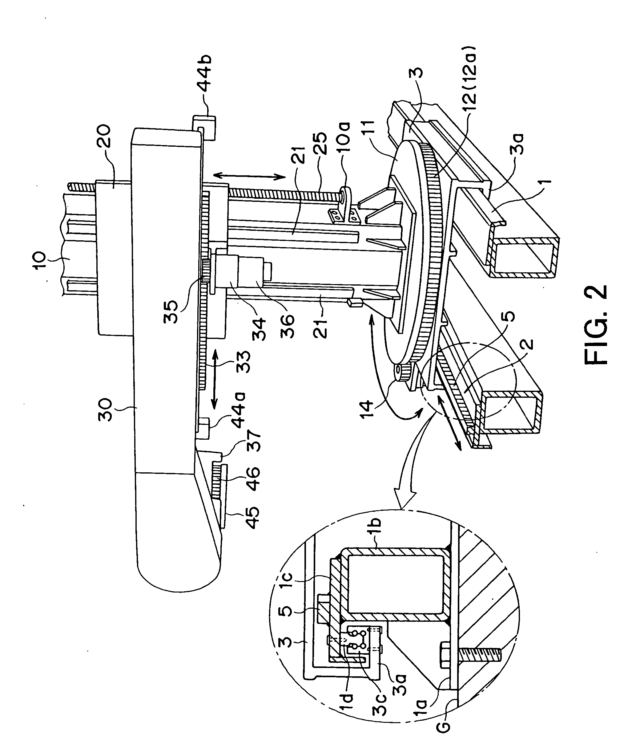
[0038] An embodiment of the transport apparatus of the present invention will be described with reference to the drawings. As shown in FIG. 1, in this transport apparatus, a table 3 is arranged so as to be capable of reciprocating on a rail 1. As shown in FIG. 2, the rail 1 includes support legs 1a to the upper sides of which support stands 1b are fixed by a fixing means, such as welding, and rail support members 1c are fixed to the upper sides of the support stands 1b so as to protrude sidewise, with linear guide rails 1d being fixed to the lower sides of the rail support members 1c by fixing means, such as bolts. As shown in FIG. 2, the outer side end portions of the table 3 are bent downwardly into a U-shape to form bearing support portions 3a, and linear guide bearings 3c are fixed to the upper side of the bearing support portions 3a by a fixing means, such as bolts. Through fit-engagement of the linear guide bearings 3c and the linear guide rails 1d, the table 3 can reciprocate...


PUM


Abstract

A transport apparatus includes a table capable of making a lateral reciprocating movement; a column arranged upright on the table so as to be capable of making normal and reverse rotation; an arm protruding sidewise from the column, the arm being capable of making a lateral reciprocating movement and ascending and descending along the column; a head mounted to the tip of the arm so as to be capable of making normal and reverse rotation; and a jig mounting stage mounted to the head so as to be capable of making normal and reverse rotation, thus allowing six-axis movements. A welding robot or a workpiece can be carried on the jig mounting stage and transported while being grasped, and the six-axis movements can be stopped at desired positions, making it possible to perform positioning on the welding robot or the workpiece in terms of orientation, height, etc.

Description

BACKGROUND OF THE INVENTION [0001] 1. Field of the Invention [0002] The present invention relates to a transport apparatus capable, for example, of holding or bearing a heavy object, in particular, a heavy article weighing 1 ton or more, such as a heavy load, product, or workpiece (hereinafter referred to as an “article”), setting it at a predetermined position (i.e., setting it in position), or bearing a robot. [0003] 2. Related Background Art [0004] A transport apparatus (a handling robot or a material handling apparatus) has been available which, for example, moves an article within a plant, loads and unloads an article on and from a truck, or transfers an article transported by a conveyor onto another conveyor. Conventional examples of such a transport apparatus include an articulated six-axis robot and the transport apparatus by the present applicant (JP 3077753 B). [0005] A positioning apparatus (a positioner) for setting an article at the operating position (i.e., setting it ...

Claims


Application Information

Patent Timeline
IPC IPC(8): B25J5/02B25J9/04B25J19/00B66C23/00
CPCB25J9/023
Inventor TAMURA, SHUJI
Owner LINE WORKS CO LTD
Why Eureka
Try Eureka