Sliding and rotating hinge module

a technology of sliding and rotating hinges, applied in the field of sliding and rotating hinge modules, can solve the problems of increasing the potential of failure, requiring electricity to power, and the complexity of motorized hinges is typically relatively complex

Active Publication Date: 2012-08-07
SOUTHCO
View PDF27 Cites 30 Cited by
  • Summary
  • Abstract
  • Description
  • Claims
  • Application Information

AI Technical Summary

Benefits of technology

[0004]A sliding and rotating hinge module for supporting a display screen or the like, includes a bracket, a slider and a support member. The slider is capable of sliding movement relative to said bracket and said support member is capable of pivotal movement relative to the slider. A drum is rotationally supported by the bracket. A constant force spring is attached to the drum at one end and to the slider at the other end. The constant force spring is biased to wrap around the drum, the constant force spring unwrapping from the drum as the slider moves toward the retracted position. The constant force spring biases the slider toward the extended position. A damping mechanism damps the rotational motion of the drum relative to the bracket for smooth, non-abrupt movement of the slider.

Problems solved by technology

Such hinges are typically relatively complex and require electricity to power them.
The added complexity of motorized hinges provides for an increased potential of failure, whether it be mechanical failure or failure to operate due to a power outage or a broken or faulty electrical connection.
The added complexity also translates into higher costs for making, buying, using, and / or replacing the hinge.

Method used


Image

  • Sliding and rotating hinge module
  • Sliding and rotating hinge module
  • Sliding and rotating hinge module

Examples


Embodiment Construction

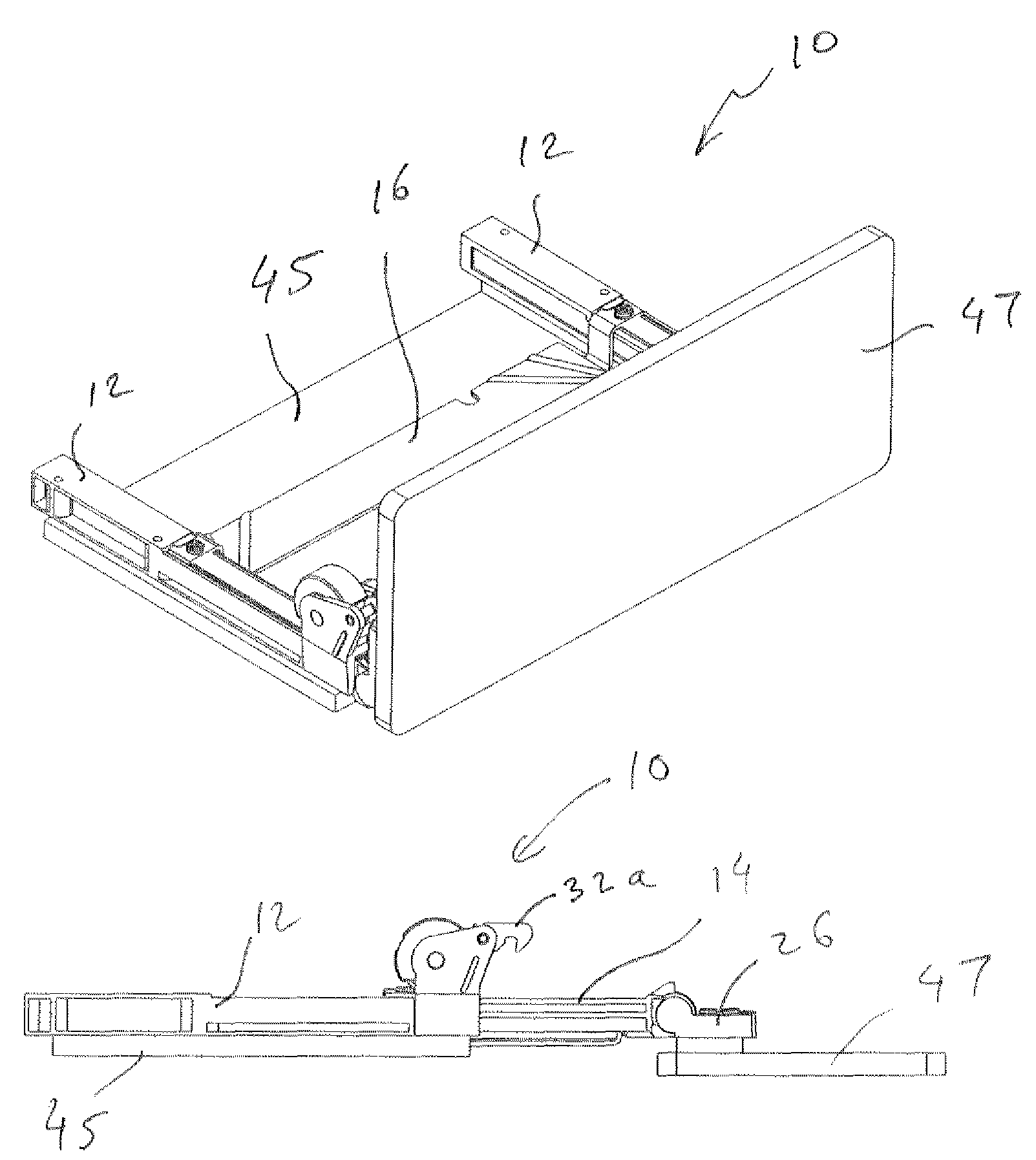
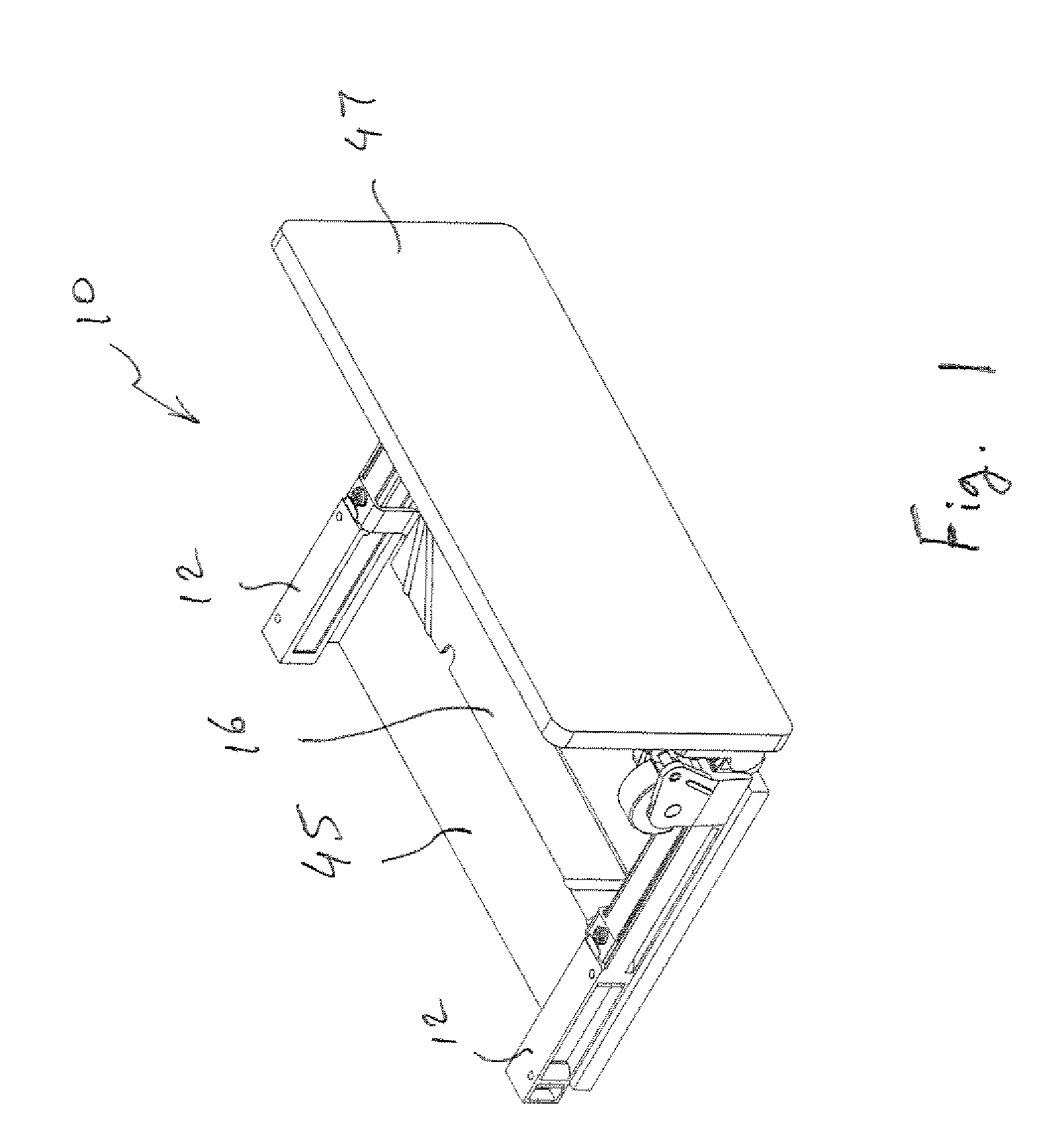
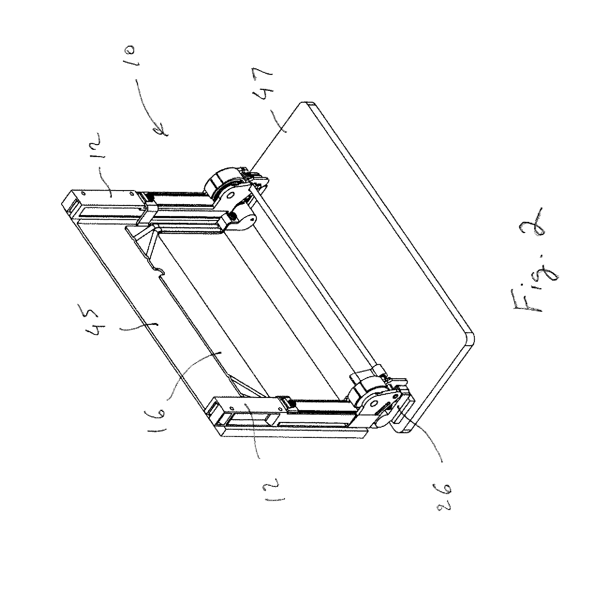
[0012]Certain terminology is used in the following description for convenience only and is not limiting. The words “right,”“left,”“upper,” and “lower” designate directions in the drawings to which reference is made. The terminology includes the words above specifically mentioned, derivatives thereof, and words of similar import.

[0013]Referring to the drawings in detail, wherein like numerals indicate like elements throughout, there is shown in FIGS. 1-88 a first embodiment of a sliding and rotating hinge module, indicated generally at 10, in accordance with the present invention. The hinge module 10 includes fixed channel brackets 12 which are fastened to a vehicle (a portion 45 of the vehicle instrument panel is shown) or an object (not shown) in which the hinge module 10 is to be used. Preferably, there are two fixed brackets 12, although it is within the spirit and scope of the present invention that there be more or less than two fixed brackets 12. The two fixed brackets 12 are ...


PUM


Abstract

A sliding and rotating hinge module for supporting a display screen or the like, includes a bracket, a slider and a support member. The slider is capable of sliding movement relative to the bracket and the support member is capable of pivotal movement relative to the slider. A drum is rotationally supported by the bracket. A constant force spring is attached to the drum at one end and to the slider at the other end. The constant force spring is biased to wrap around the drum, the constant force spring unwrapping from the drum as the slider moves toward the retracted position. The constant force spring biases the slider toward the extended position. A damping mechanism damps the rotational motion of the drum relative to the bracket for smooth, non-abrupt movement of the slider.

Description

CROSS REFERENCE TO RELATED APPLICATIONS[0001]This application claims the benefit of the priority of, and is the non-provisional of, U.S. provisional application for patent Ser. No. 60 / 891,039, filed on Feb. 21, 2007, the entirety of which is incorporated herein by reference.BACKGROUND OF THE INVENTION[0002]This invention generally relates to hinge modules and, more particularly, to a sliding and rotating hinge module.[0003]Typically, hinges that provide constant-speed sliding and rotating motion have required motors or other actuators to do so. Such hinges are typically relatively complex and require electricity to power them. The added complexity of motorized hinges provides for an increased potential of failure, whether it be mechanical failure or failure to operate due to a power outage or a broken or faulty electrical connection. The added complexity also translates into higher costs for making, buying, using, and / or replacing the hinge. It would be desirable to have a less comp...

Claims


Application Information

Patent Timeline
Patent Type & Authority Patents(United States)
IPC IPC(8): E05D7/06
CPCB60R11/0235B60R2011/0003B60R2011/0082B60R2011/0084B60R2011/0085B60R2011/0092Y10T16/5285E05F1/16E05Y2201/21E05Y2201/254E05Y2201/266Y10T16/5323E05D15/0604
Inventor ANDERSON, GLENN E.
Owner SOUTHCO
Why Eureka
Try Eureka