
Machine core structure of heavy load holder

A technology of a gimbal and movement, applied in the field of cameras, can solve the problems such as the misalignment of the occlusal surfaces of the horizontal worm gear and the horizontal worm, affecting the horizontal image quality of the camera, affecting the smoothness and stability of the heavy-duty gimbal, and solving the error gap of the worm gear and the worm. , smooth rotation, good horizontal image quality effect

Inactive Publication Date: 2011-06-15
TIANJIN TIANDY DIGITAL TECH
View PDF4 Cites 16 Cited by
  • Summary
  • Abstract
  • Description
  • Claims
  • Application Information

AI Technical Summary

Problems solved by technology

[0010] In the heavy-duty pan-tilt of the prior art, the actual horizontal image effect of the mounted camera depends on the stability of the heavy-duty pan-tilt when it rotates in the horizontal direction, and the horizontal rotation stability of the heavy-duty pan-tilt depends on the level of movement in the movement. The coordination between the driving mechanism and the horizontal transmission mechanism, because the processing of each component is carried out separately, in the actual processing process, the problem that the occlusal surfaces of the horizontal worm wheel and the horizontal worm often do not overlap often occurs, and there will be some problems in the cooperation between the two. error
Moreover, during the use of the heavy-duty head, due to long-term wear and tear, there will be gaps between the horizontal worm and the horizontal worm wheel, which will affect the smoothness and stability of the heavy-duty head in the horizontal direction, and thus affect the Horizontal image quality of the camera

Method used


Image

  • Machine core structure of heavy load holder
  • Machine core structure of heavy load holder
  • Machine core structure of heavy load holder

Examples


Embodiment Construction

[0023] The present invention will be described in detail below with reference to the drawings and examples.

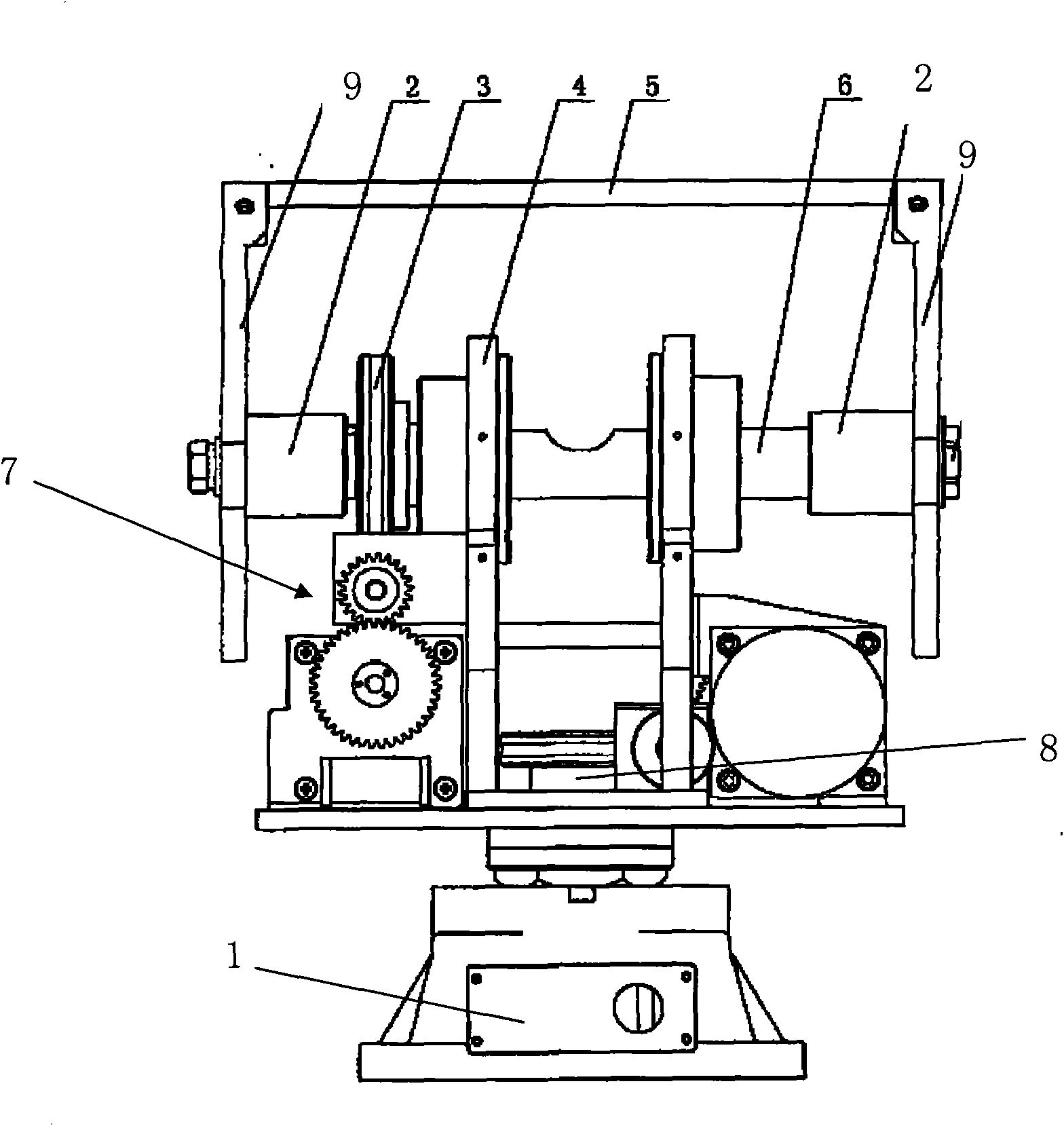
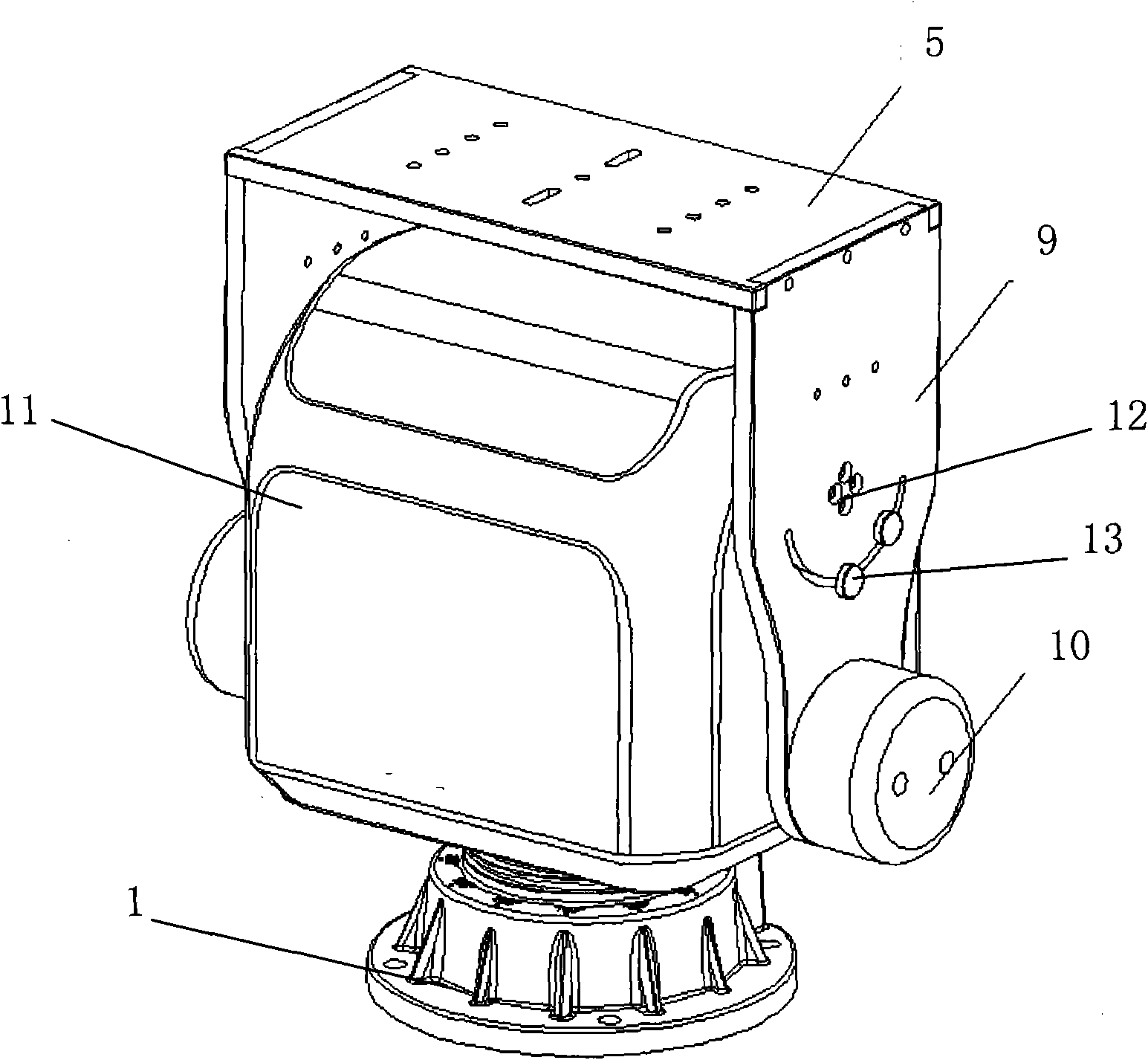
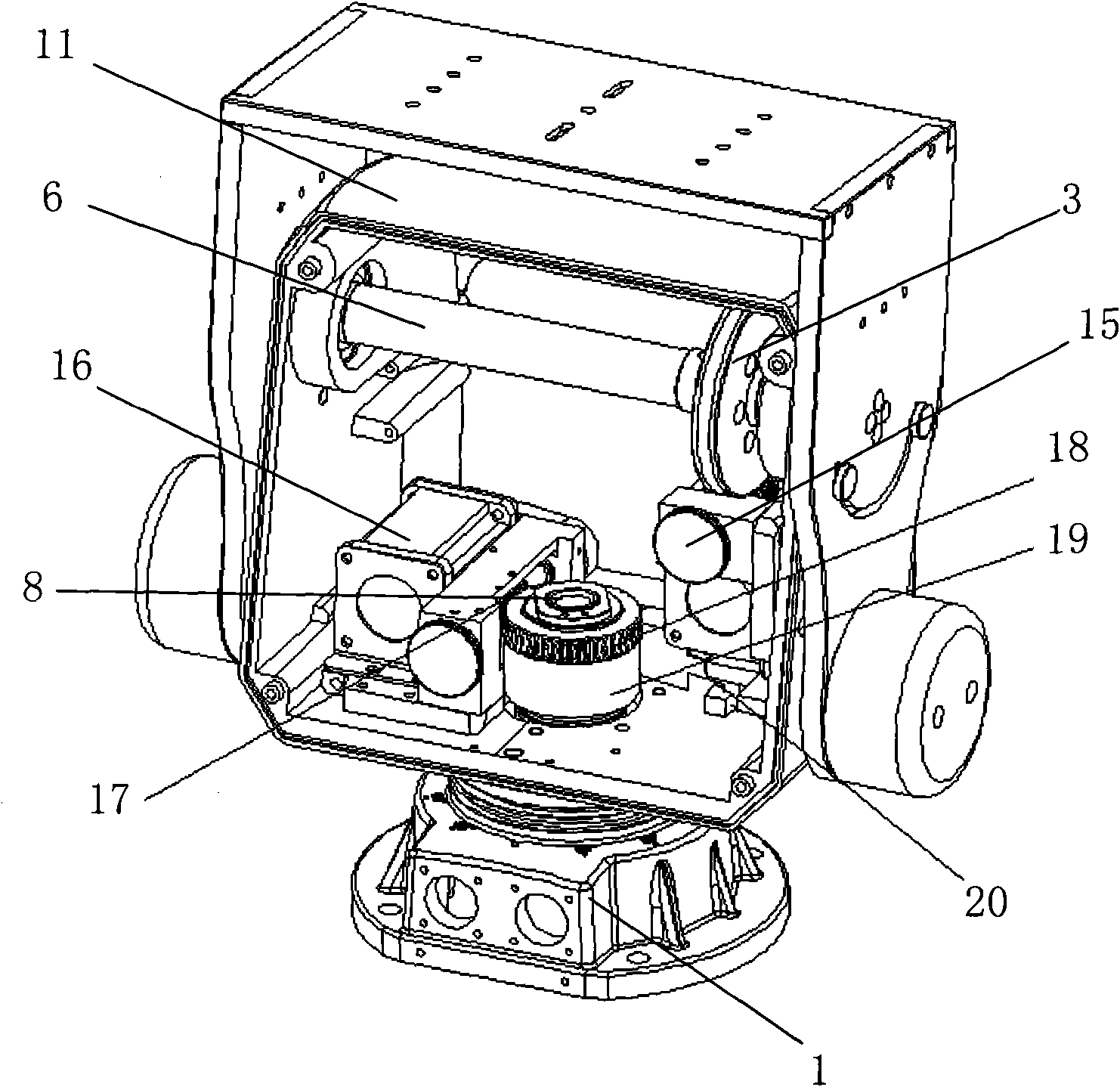
[0024] figure 2 It is a structural representation of the heavy-duty platform of the present invention; image 3 It is a schematic diagram of the movement structure of the heavy-duty platform of the present invention; Figure 4 It is a plan view of the movement structure of the heavy-duty platform of the present invention in the horizontal worm gear part.

[0025] Such as Figure 2 to Figure 4 As shown, the heavy-duty pan / tilt includes: base 1, fixed to the preset position of the camera, supporting the heavy-duty pan / tilt and the camera; The fixed camera rotates vertically and horizontally; the casing 11 is arranged outside the core to surround and protect the core; the shield is connected by the end plates 9 respectively arranged on both sides of the shell and the shields connecting the end plates plate 5, the camera is fixed on the shield connecting plate, and mu...


PUM


Abstract

The invention relates to a machine core structure of a heavy load holder. The heavy load holder comprises a base, a machine core, a driving mechanism, a shell and a protecting cover; an elastic fixing part connected with the horizontal drive shaft and the inner wall of the shell is fixed on a horizontal drive shaft; the position of the horizontal drive shaft is limited by the elastic fixing part so that a horizontal worm screw and a horizontal worm gear keep close fit and keep stable running in fit. The tension generated by a constant force spring effectively solves the machining and abrading errors of the worm gear and the worm screw and can overcome the machining error of the horizontal worm gear and the horizontal worm screw and the abrading error after the horizontal worm gear and the horizontal worm screw run for a period of time so that the occlusal surfaces of the horizontal worm gear and the horizontal worm screw keep coincided all the time in the driving process; therefore, the error clearance of the worm gear and the worm screw is effectively solved, the heavy load holder smoothly runs on the horizontal direction, the stability of a camera in rotatably working is ensured, and the quality of horizontal images of the camera is better.

Description

technical field [0001] The present invention relates to the technical field of cameras, specifically, an elastic fixing part is arranged on a horizontal transmission shaft, and the position of the horizontal transmission shaft is limited by the elastic fixing part, so that the horizontal worm wheel and the horizontal worm maintain a close fit state and ensure the horizontal image of the camera. The movement structure of the stable heavy-duty gimbal. Background technique [0002] The PTZ is a camera installation platform composed of two AC motors, which can drive the camera to move horizontally and vertically. There are two motors inside the gimbal, which are responsible for the up and down and left and right rotations of the gimbal respectively. The difference in working voltage also determines the overall working voltage of the gimbal, generally there are AC 24V, AC 220V and DC 24V. When receiving the up and down action voltage, the vertical motor rotates and drives the v...

Claims


Application Information

Patent Timeline
IPC IPC(8): F16M11/12
Inventor 戴林周平
Owner TIANJIN TIANDY DIGITAL TECH
Learn More