Directional control method for dual brush robotic pool cleaners

a technology of robotic pool cleaners and drive motors, which is applied in the direction of process and machine control, cleaning using liquids, instruments, etc., can solve the problems of increased manufacturing costs, increased manufacturing costs, and increased maintenance costs of pool cleaners

Active Publication Date: 2012-08-14
ZODIAC POOL SYST LLC
View PDF27 Cites 22 Cited by
  • Summary
  • Abstract
  • Description
  • Claims
  • Application Information

AI Technical Summary

Benefits of technology

[0012]The direction of rotation of the drive motor, and thereby the direction of movement of the pool cleaner, is determined by the programmed processor and associated controller. When the direction of the drive motor is changed, the rotational delay clutch disengages the driven brush from the adjacent free brush for a predetermined degree or amount of arcuate movement or rotation by the driven brush. The free brush stops moving for a predetermined number of partial and / or full turns of the driven brush. This has the effect of causing a turning or pivoting movement around the stationary free brushes.
[0053]In yet another embodiment, the pool cleaner is equipped with a switch that is mounted on or positioned proximate the interior surface of the housing. The switch is electrically coupled to the controller and upon being actuated, sends a signal to the controller, which causes an increase in the distance that the pool cleaner is propelled during its travel on the bottom surface between the opposing sidewalls. This can be accomplished by increasing the time, and therefore the distance before the drive-motor is stopped and reversed.

Problems solved by technology

In many cases, the pattern of movement is random and the pool cleaner must be operated for many hours, and even then with no real assurance that some surfaces will not be missed.
As will be understood by one of ordinary skill in the art, the cost associated with the design and assembly of a pool cleaner having more than one drive motor is significant.
When this is combined with the expense associated with the design and fabrication of integrated circuit devices and processors embodying complex programs and algorithms and the associated controllers, it will be apparent that additional substantial expenses will be incurred.
Moreover, the mechanical linkages associated with the dual drive motors are sources of wear and potential failure that require maintenance.

Method used


Image

  • Directional control method for dual brush robotic pool cleaners
  • Directional control method for dual brush robotic pool cleaners
  • Directional control method for dual brush robotic pool cleaners

Examples


first embodiment

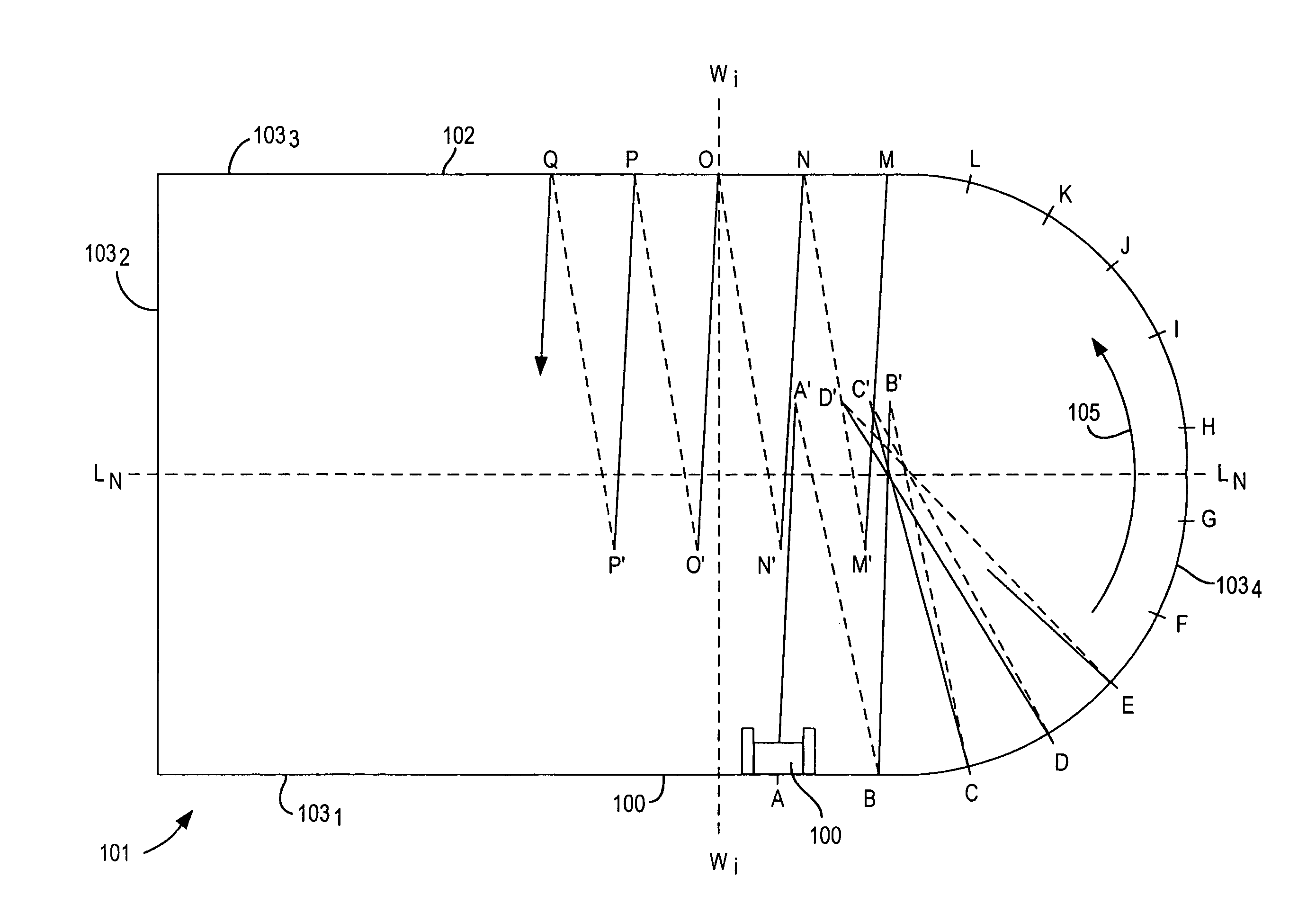
[0114]Referring to FIG. 17, a schematic diagram of a controller 160 and a switch 150 for manually controlling the distance the pool cleaner 100 is propelled between opposing sidewalls 103 is shown. The controller 160 and switch 150 operate in accordance with the principles of the cleaning pattern shown in FIG. 16.

[0115]The controller 160 is installed in the watertight container mounted on the interior of the chassis 130. The switch 150 is electrically connected to the controller 160 and enables an end-user to manually change specific program settings which are associated with the distance that the pool cleaner is propelled before it stops to turn and reverse direction, as described above with respect to the cleaning pattern of FIG. 16.

[0116]The controller 160 comprises a processor 162 and memory 128 for storing various control programs 129. The processor 162 may be any conventional processor, such as one or more INTEL processors or a conventional micro-controller. The memory 128 can...

second embodiment

[0123]Referring to FIG. 18, a schematic diagram is shown of a switch for manually controlling the movement of the pool cleaner in accordance with the principles of FIG. 16. FIG. 18 is the same as FIG. 17, except that the switch 150 is preferably implemented as a reed switch 152 that is actuated by utilizing a magnet 154.

[0124]The reed switch 152 can be a conventional reed switch that includes two ferromagnetic blades which are typically hermetically sealed in a glass capsule. In one embodiment, the ends of the blades overlap in the capsule to form a gap, such that the reed switch is in a non-conductive (open) state. Upon application of a suitable magnetic field, the ends of the opposing blades come into contact with each other to form a closed circuit. The reed blades act as magnetic flux conductors when exposed to an external magnetic field from either a permanent magnet or an electromagnetic coil, as conventionally known in the art.

[0125]The reed switch 152 is mounted on the inner...

third embodiment

[0135]In the invention, a switch, such as a rotatable or push button switch, or reed switch and magnet is provided to incrementally increase the time, and consequently, the distance the pool cleaner traverses between opposing side walls before turning and reversing direction. In this manner, the end-user can manually change the factory or dealer program settings to increase the coverage between opposing side walls before the pool cleaner turns and reverses direction. The end-user can control the programming of the pool cleaner to provide greater cleaning coverage, which is especially advantageous in instances where the pool is irregular shaped or over-sized.

[0136]It is noted that method 1500, the pool cleaning pattern of FIG. 16, and the embodiments of FIGS. 17 and 18 for controlling the distance that the pool cleaner traverses in a direction away from a sidewall is also applicable to a pool cleaner that is equipped with a pair of opposing wheels, rollers or other type of rotational...


PUM


Abstract

A method for accurately controlling the directional and turning movement of a self-propelled robotic pool cleaner while cleaning a pool includes the steps of propelling the pool cleaner in a first direction along a generally straight path from a first sidewall toward an opposing sidewall of the pool, wherein said pool cleaner is propelled to a position in the pool corresponding to a distance greater than the midpoint between the first sidewall and the opposing sidewall and before contacting the opposing sidewall of the pool; stopping the pool cleaner at the position and pivoting the pool cleaner to a predetermined angular change in direction; and reversing direction and resuming propulsion of the pool cleaner, wherein the pool cleaner moves in a second direction along a generally straight path that is angularly displaced from the first direction.

Description

CROSS REFERENCE TO RELATED APPLICATION[0001]This patent application is a Continuation-in-Part of U.S. patent application Ser. No. 10 / 542,158, filed Mar. 23, 2006, now U.S. Pat. No. 7,849,547, which claims priority to International Application No. PCT / US2004 / 037148, filed on Nov. 4, 2004, which claims the benefit of U.S. Provisional Application Ser. No. 60 / 517,352, filed Nov. 4, 2003, the contents of all of which are incorporated by reference herein.FIELD OF THE INVENTION[0002]This invention relates to the directional control of self-propelled automated pool and tank cleaners that are supported by moving rotational support members positioned at opposing ends of the cleaner housing.BACKGROUND OF THE INVENTION[0003]A wide variety of methods and apparatus for controlling the patterns of movement of tank and swimming pool cleaners have been disclosed in the prior art. The overriding purpose of these controls is to assure that the cleaner passes over substantially the entire surface to be...

Claims


Application Information

Patent Timeline
Patent Type & Authority Patents(United States)
IPC IPC(8): B08B7/04E04H4/16
CPCE04H4/1654G05D1/0219G05D2201/0203A46B13/02A46B13/00
Inventor ERLICH, GIORAHORVATH, TIBOR
Owner ZODIAC POOL SYST LLC
Why Eureka
Try Eureka