Method of and device for generating and processing parameters representing HRTFs

a technology of parameters and generating devices, applied in the direction of broadcast circuit arrangements, broadcast system receiving, broadcast with distribution, etc., can solve the problem of significant inter-aural time delay that can be noticed

Active Publication Date: 2012-08-14
KONINKLIJKE PHILIPS ELECTRONICS NV
View PDF22 Cites 11 Cited by
  • Summary
  • Abstract
  • Description
  • Claims
  • Application Information

AI Technical Summary

Benefits of technology

[0019]The characterizing features according to the invention particularly have the advantage that Head-Related Transfer Functions (HRTFs) are represented by simple parameters leading to a reduction of computational complexity when applied to audio signals.
[0021]According to an advantageous aspect of the invention, multiple simultaneous sound sources may be synthesized with a processing complexity that is roughly equal to that of a single sound source. With a reduced processing complexity, real-time processing is advantageously possible, even for a large number of sound sources.
[0023]Furthermore, the amount of data to represent the HRTFs is significantly reduced, resulting in reduced storage requirements, which in fact is an important issue in mobile applications.
[0037]In yet another aspect of the invention, the parameters mentioned above may be transmitted across devices. This has the advantage that every audio-rendering device (PC, laptop, mobile player, etc.) may be personalized. In other words, somebody's own parametric data is obtained that is matched to his or her own ears without the need of transmitting a large amount of data as in the case of conventional HRTFs. One could even think of downloading parameter sets over a mobile phone network. In that domain, transmission of a large amount of data is still relatively expensive and a parameterized method would be a very suitable type of (lossy) compression.
[0038]In still another embodiment, users and listeners could also exchange their HRTF parameter sets via an exchange interface if they like. Listening through someone else's ears may be made easily possible in this way.

Problems solved by technology

Furthermore, because of the finite speed of sound in air, the significant inter-aural time delay can be noticed, depending on the sound source position.

Method used


Image

  • Method of and device for generating and processing parameters representing HRTFs
  • Method of and device for generating and processing parameters representing HRTFs
  • Method of and device for generating and processing parameters representing HRTFs

Examples


Embodiment Construction

[0048]The illustrations in the drawings are schematic. In different drawings, similar or identical elements are denoted by the same reference signs.

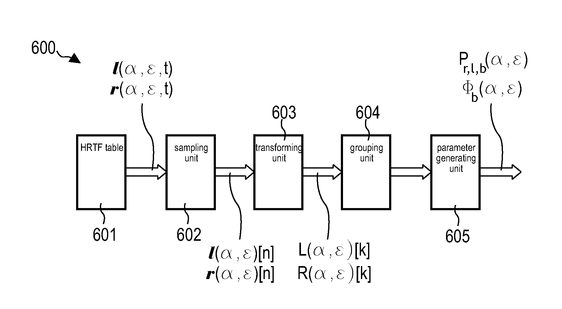
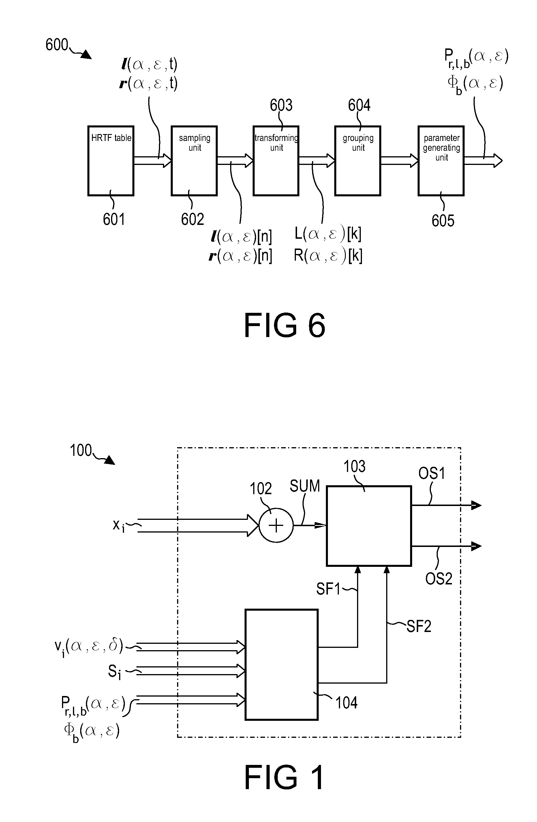
[0049]A device 600 for generating parameters representing Head-Related Transfer Functions (HRTFs) will now be described with reference to FIG. 6.

[0050]The device 600 comprises an HRTF-table 601, a sampling unit 602, a transforming unit 603, a splitting unit 604 and a parameter-generating unit 605.

[0051]The HRTF-table 601 has stored at least a first time-domain HRTF impulse response signal l(α,ε,t) and a second time-domain HRTF impulse response signal r(α,ε,t) both belonging to the same spatial position. In other words, the HRTF-table has stored at least one time-domain HRTF impulse response pair (l(α,ε,t), r(α,ε,t)) for virtual sound source position. Each impulse response signal is represented by an azimuth angle α and an elevation angle ε. Alternatively, the HRTF-table 601 may be stored on a remote server and HRTF impulse response pairs...


PUM


Abstract

A method of generating parameters representing Head-Related Transfer Functions, the method comprising the steps of a) sampling with a sample length (n) a first time-domain HRTF impulse response signal using a sampling rate (fs) yielding a first time-discrete signal, b) transforming the first time-discrete signal to the frequency domain yielding a first frequency-domain signal, c) splitting the first frequency-domain signal into sub-bands, and d) generating a first parameter of the sub-bands based on a statistical measure of values of the sub-bands.

Description

FIELD OF THE INVENTION[0001]The invention relates to a method of generating parameters representing Head-Related Transfer Functions.[0002]The invention also relates to a device for generating parameters representing Head-Related Transfer Functions.[0003]The invention further relates to a method of processing parameters representing Head-Related Transfer Functions.[0004]Moreover, the invention relates to a program element.[0005]Furthermore, the invention relates to a computer-readable medium.BACKGROUND OF THE INVENTION[0006]As the manipulation of sound in virtual space begins to attract people's attention, audio sound, especially 3D audio sound, becomes more and more important in providing an artificial sense of reality, for instance, in various game software and multimedia applications in combination with images. Among many effects that are heavily used in music, the sound field effect is thought of as an attempt to recreate the sound heard in a particular space.[0007]In this contex...

Claims


Application Information

Patent Timeline
Patent Type & Authority Patents(United States)
IPC IPC(8): H04R5/00H04B15/00H04H20/47H04R5/02
CPCH04R25/552H04S1/002H04S2420/01H04S1/00
Inventor BREEBAART, JEROEN DIRKVAN LOON, MICHEL MACHIEL WILLEM
Owner KONINKLIJKE PHILIPS ELECTRONICS NV
Why Eureka
Try Eureka