Illuminated push button switch

a push button switch and illumination technology, applied in the direction of emergency actuators, sewing machine control devices, textiles and paper, etc., can solve the problems of low operability of the first switch device, difficult to uniformly illuminate the whole poor operation feeling, so as to achieve uniform illumination of the surface of the push button member, simple structure, and good operation feeling

Active Publication Date: 2012-08-21
BROTHER KOGYO KK
View PDF15 Cites 8 Cited by
  • Summary
  • Abstract
  • Description
  • Claims
  • Application Information

AI Technical Summary

Benefits of technology

[0014]Therefore, an object of the present disclosure is to provide a push button switch device which can provide a good operation feeling and can uniformly illuminate the surface of the push button member by employment of a simpler structure.

Problems solved by technology

As a result, the first switch device has a low operability, for example, providing a bad operation feeling when the user depresses the push button member.
Accordingly, it is difficult to uniformly illuminate the whole surface of the push button member.
Thus, the second switch device lacks in uniformity of brightness, resulting in a defect of low visual effect.
However, provision of the mask member increases the number of components and complicates the structure of the switch device.

Method used


Image

  • Illuminated push button switch
  • Illuminated push button switch
  • Illuminated push button switch

Examples


first example

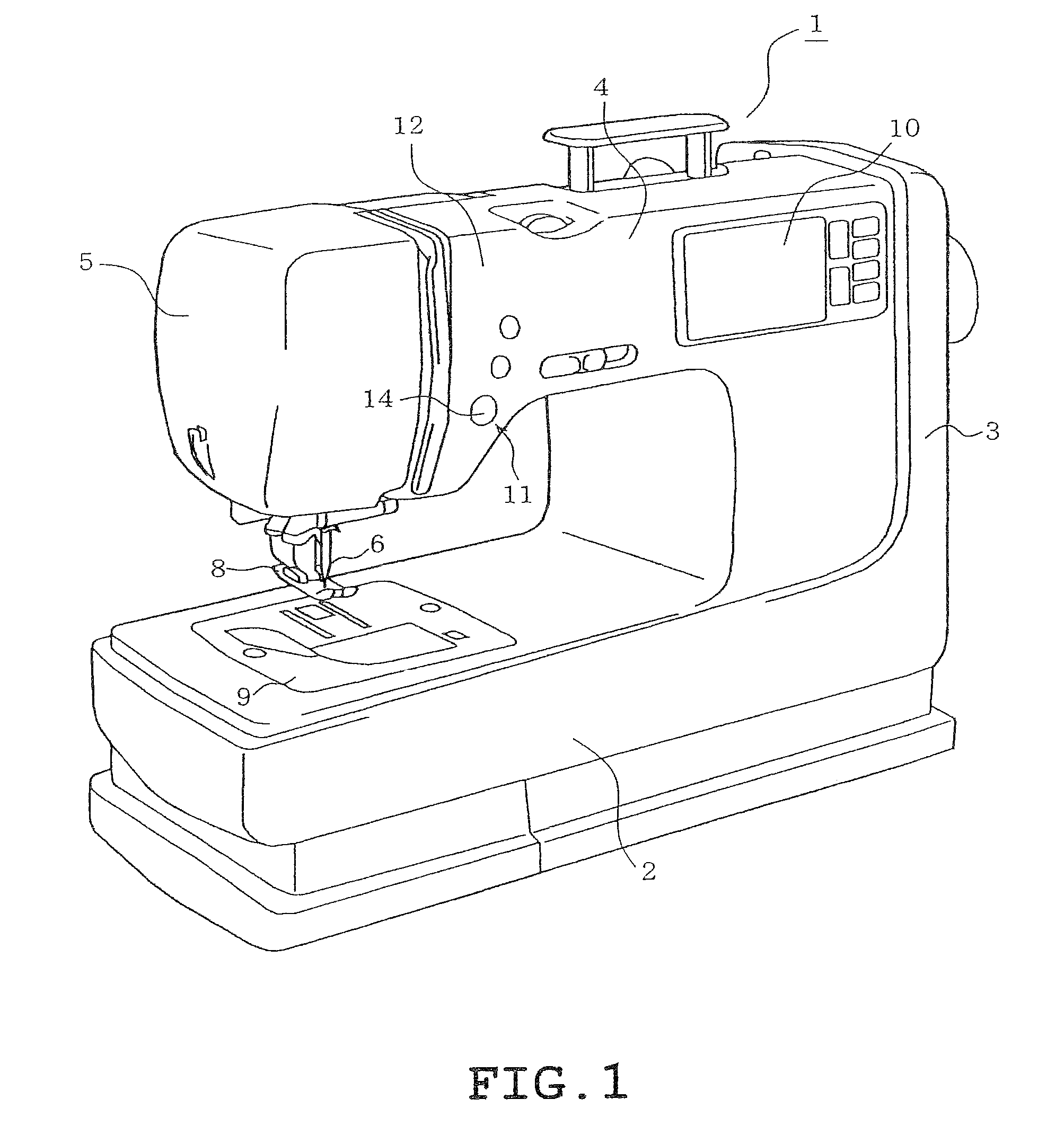
[0036]A first example will be described with reference to FIGS. 1 to 7. The push button switch device is employed in a household sewing machine in the first example.

[0037]Firstly, a body 1 of the household sewing machine serves as an equipment body and will be described with reference to FIG. 1. The sewing machine body 1 includes a bed 2 extending in the right-left direction in FIG. 1, a pillar 3 standing on a right end of the bed 2, and an arm 4 extending leftward from an upper end of the pillar 3 in FIG. 1. The bed 2, pillar 3 and arm 4 are formed integrally with the sewing machine body 1. The arm 4 has a distal end serving as a sewing machine head 5. The head 5 is provided with a needle bar (not shown) movable upward and downward. A needle 6 is attached to a distal (or lower) end of the needle bar. A presser foot 8 is also mounted on the needle bar. A drive mechanism is provided in the sewing machine body 1 to drive the needle bar and the like. A sewing machine motor (not shown) ...


PUM


Abstract

A push button switch device includes a push button disposed on a cover constituting an outer surface of an equipment body and light-transmissible, a switching element behind the push button so that its operation axis substantially corresponds with a central axis of the push button, light sources around the switching element to illuminate the push button and operated by the push button, and an incidence surface on a rear surface of the push button so that light from the light sources is incident on it and including a concave curved surface located so as to face the light sources and a convex curved surface located outside and continuous to the concave curved surface. The push button has a recess in a central rear surface so as to be located inside the incidence surface and a light scattering surface on an inner surface of the recess so as to scatter light.

Description

CROSS-REFERENCE TO RELATED APPLICATIONS[0001]This application is based on and claims the benefit of priority from the prior Japanese Patent Application No. 2009-139105, filed on Jun. 10, 2009, the entire contents of which are incorporated herein by reference.BACKGROUND[0002]1. Field[0003]The present disclosure relates to a push button switch device including a self-illumination push button member, and a sewing machine provided therewith.[0004]2. Related Art[0005]A household sewing machine includes a push button switch device, such as a start / stop switch, provided on the front of an arm constituting a sewing machine body, for example. The push button switch device of the aforementioned type comprises a push button member which is mounted on a cover constituting the front of the arm so as to be depressible. With this, a switching element such as a “tact switch” (a registered trademark) is mounted on a substrate provided inside the cover, so as to be actuated by the push button member....

Claims


Application Information

Patent Timeline
Patent Type & Authority Patents(United States)
IPC IPC(8): H01H9/00
CPCD05B69/04D05B79/00H01H13/023D05D2205/08H01H13/83H01H2219/014H01H2219/056H01H2221/07H01H2229/046H01H2231/014
Inventor OMINATO, HIROYUKI
Owner BROTHER KOGYO KK
Why Eureka
Try Eureka