Zipper hole punch treatment

a hole punch and punching technology, applied in the field of punching punching treatment, to achieve the effect of little or no damage to the profil

Inactive Publication Date: 2012-08-28
ILLINOIS TOOL WORKS INC
View PDF5 Cites 2 Cited by
  • Summary
  • Abstract
  • Description
  • Claims
  • Application Information

AI Technical Summary

Benefits of technology

[0006]It is therefore an object of the present disclosure to provide a method and apparatus wherein apertures may be punched or otherwise formed in zipper profiles and a separator bar, pin, or similar device is used to separate in zipper profiles with little or no damage to the profiles.
[0008]The advantages typically achieved by this configuration include allowing double profile zippers with larger masses to run in the automated manufacturing machinery, lessening the web breakage of zippers, allowing faster operating speeds thereby resulting in more bags or packages per minute, and allowing a zipper with greater opening forces (i.e., profiles more tightly fastened with each other) to run in the automated manufacturing machinery.

Problems solved by technology

This deformation or “smashing” of the interlocking elements disrupts the interlocking of the interlocking elements thereby resulting in the separator bar, pin, or similar device being more likely to separate the profiles without creating a collision or damage to the zipper.

Method used


Image

  • Zipper hole punch treatment
  • Zipper hole punch treatment
  • Zipper hole punch treatment

Examples


Embodiment Construction

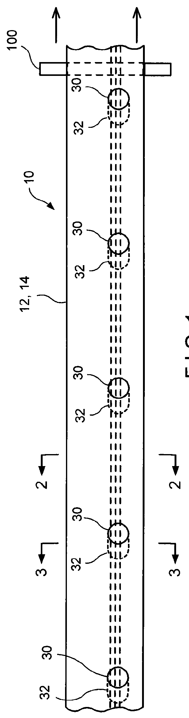
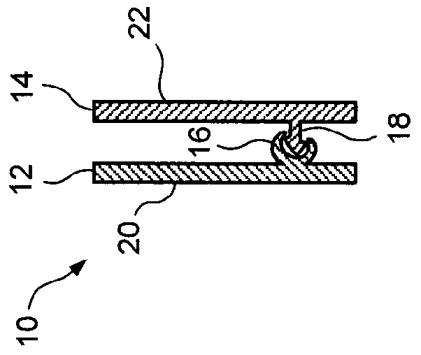
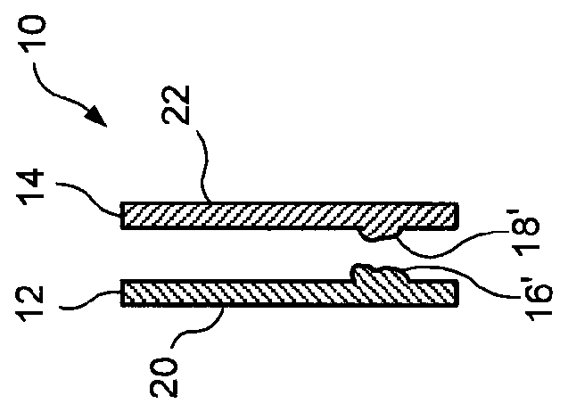
[0013]Referring now to the drawings in detail wherein like numerals indicate like elements throughout the several views, one sees that FIG. 1 is a schematic of the reclosable zipper 10 of the present disclosure. As shown in FIG. 2, reclosable zipper 10 includes first and second profiles 12, 14. First profile 12 includes first interlocking element 16 (configured as a female element) and first flange 20 extending therefrom, while second profile 14 include second interlocking element 18 (configured as a male element) and second flange 22 extending therefrom. Apertures or holes 30 are periodically formed in reclosable zipper 10 so as to pass through the interlocking elements 16, 18. Apertures or holes 30 are typically spaced at package-width intervals so that side seals of resulting packages or bags (not shown) can be formed over the apertures or holes 30 in order to facilitate a flat and hermetic side seal at the zipper area. Immediately upstream of apertures 30, areas of profile defor...


PUM


Abstract

The disclosure relates to a reclosable zipper for a package or bag wherein apertures are formed at periodic package-width intervals passing through the interlocking elements of the zipper profiles in order to minimize the mass of zipper material in areas where side seals of packages or bags will be subsequently formed. The otherwise interlocking elements upstream of, or at the trailing edge of, the apertures are deformed so as to prevent interlocking of the elements through a limited area. This allows a separator pin to pass through the area of the apertures and pass between the zipper profiles, eliminating or reducing the collision of the separator with the zipper profiles and subsequent potential damage to the zipper profiles.

Description

[0001]This application claims priority under 35 U.S.C. §119(e) of U.S. provisional application Ser. No. 61 / 115,611 filed Nov. 18, 2008, the disclosure of which is hereby incorporated by reference.BACKGROUND OF THE INVENTION[0002]1. Field of the Disclosure[0003]The present disclosure pertains to the punching of holes or apertures into the zipper of a reclosable package wherein a portion of the zipper profile is deformed, smashed or otherwise splayed to improve the opening characteristics of the zipper.[0004]2. Description of the Prior Art[0005]In the prior art, it is known to punch holes or apertures into a zipper to remove part of the interlocking profile. The removal of a portion of the zipper profile aids in the side seal creation in that a flat and hermetic side seal at the zipper area may be facilitated by removing the mass of material associated with the profile and leaving the web material of the zipper in place. However, when the holes or apertures are punched into a zipper w...

Claims


Application Information

Patent Timeline
Patent Type & Authority Patents(United States)
IPC IPC(8): A44B19/16
CPCB31B19/14B31B19/90B65D33/2558B65D33/2508B31B2219/14B31B2219/9019Y10T24/2534Y10T24/2516Y10T24/45168Y10T24/2532B31B70/14B31B70/8132
Inventor GRECO, CHARLES G.
Owner ILLINOIS TOOL WORKS INC
Why Eureka
Try Eureka