Advanced flushing for workpiece erosion

a technology for workpieces and flushing, applied in welding apparatuses, electrical-based machining electrodes, manufacturing tools, etc., can solve problems such as significant consumption of drill bits, inability to directly remove, and difficulty in removing fasteners and collars from the frame(s)

Active Publication Date: 2011-05-19
PERFECT POINT EDM CORP
View PDF23 Cites 3 Cited by
  • Summary
  • Abstract
  • Description
  • Claims
  • Application Information

AI Technical Summary

Benefits of technology

[0015]In some exemplary implementations, the hand held EDM and system is capable of removing at least a portion of a fastener with little or no damage to the material in which the fastener is engaged.
[0018]The device may be brought to a workpiece and operated in such a manner as to remove a sufficient part of a fastener to permit the fastener to be removed from a frame or structure without damaging the structure of the frame.

Problems solved by technology

Fasteners commonly include rivets or threaded fasteners which have been malleably distorted so they cannot be directly removed.
Removal of the fastener and collar from the frame(s) may be challenged due to the fixation of the fastener and the collar, the toughness of the materials used for fasteners and collar, and the delicate condition of surrounding frames to which they are applied.
Additionally, when the fastener is of titanium or other difficult to machine materials, such drilling results in a significant consumption of drill bits.
Traditional drilling of fasteners operation has a known risk of damage to the structure in which the fastener is engaged.
Damage to surrounding structures may result from vibration, drill bit slips, or drilling too deep.
If drill bit slippage damage occurs to the surrounding material, or if the hole should be cut too deep, an oversized fastener might be used during reassembly, or the entire component may need to be replaced.
Measures to correct such undesirable damage may result in additional expense associated with the operation.
Such diagnostics require time, may cause delay, and may result in costs.
Therefore, erosion is essentially limited to a vaporization process.

Method used


Image

  • Advanced flushing for workpiece erosion
  • Advanced flushing for workpiece erosion
  • Advanced flushing for workpiece erosion

Examples


Embodiment Construction

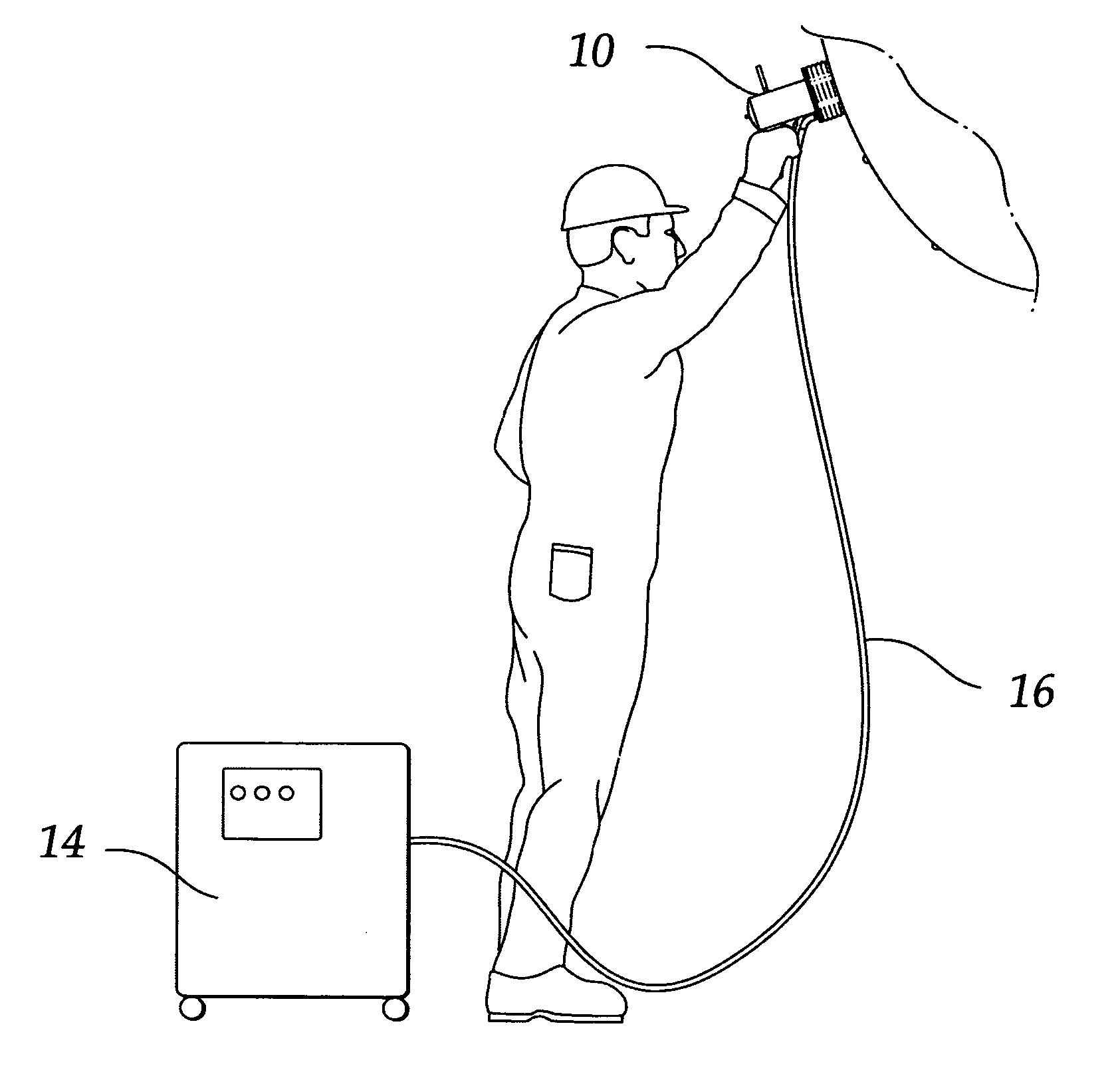
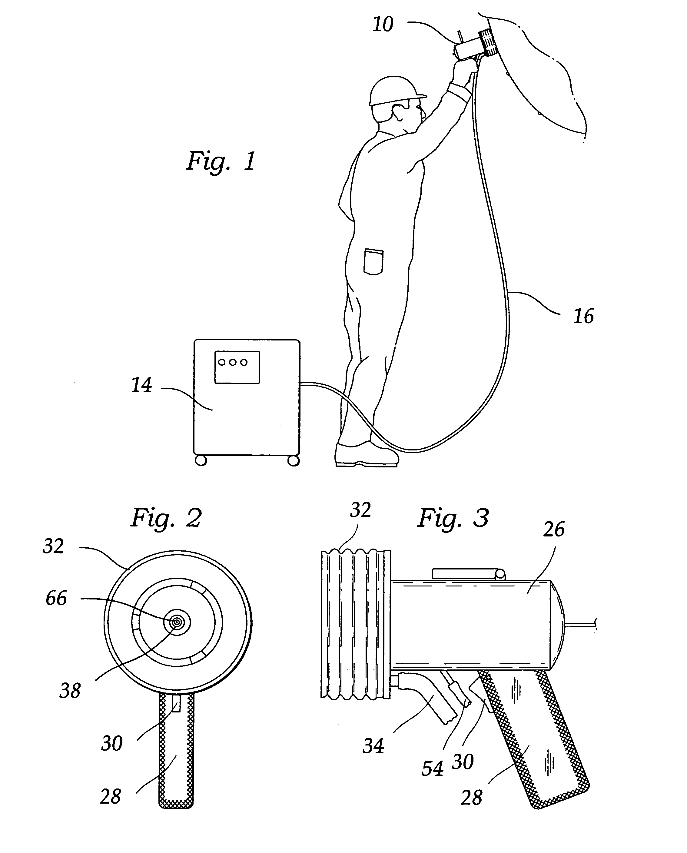
[0042]FIG. 1 shows the hand-held device 10 being hand-held by a user. In this implementation the hand-held device 10 is part of a system which supplies power, control and dielectric fluid (which may also be a coolant) via the support unit 14. Flexible umbilical 16 interconnects the hand-held device 10 and the support unit 14 so that the hand-held device can be positioned as desired.

[0043]According to some exemplary implementations, a hand-held device 10 is shown in side elevation view in FIG. 2. According to some exemplary implementations, a side view is shown in FIG. 3.

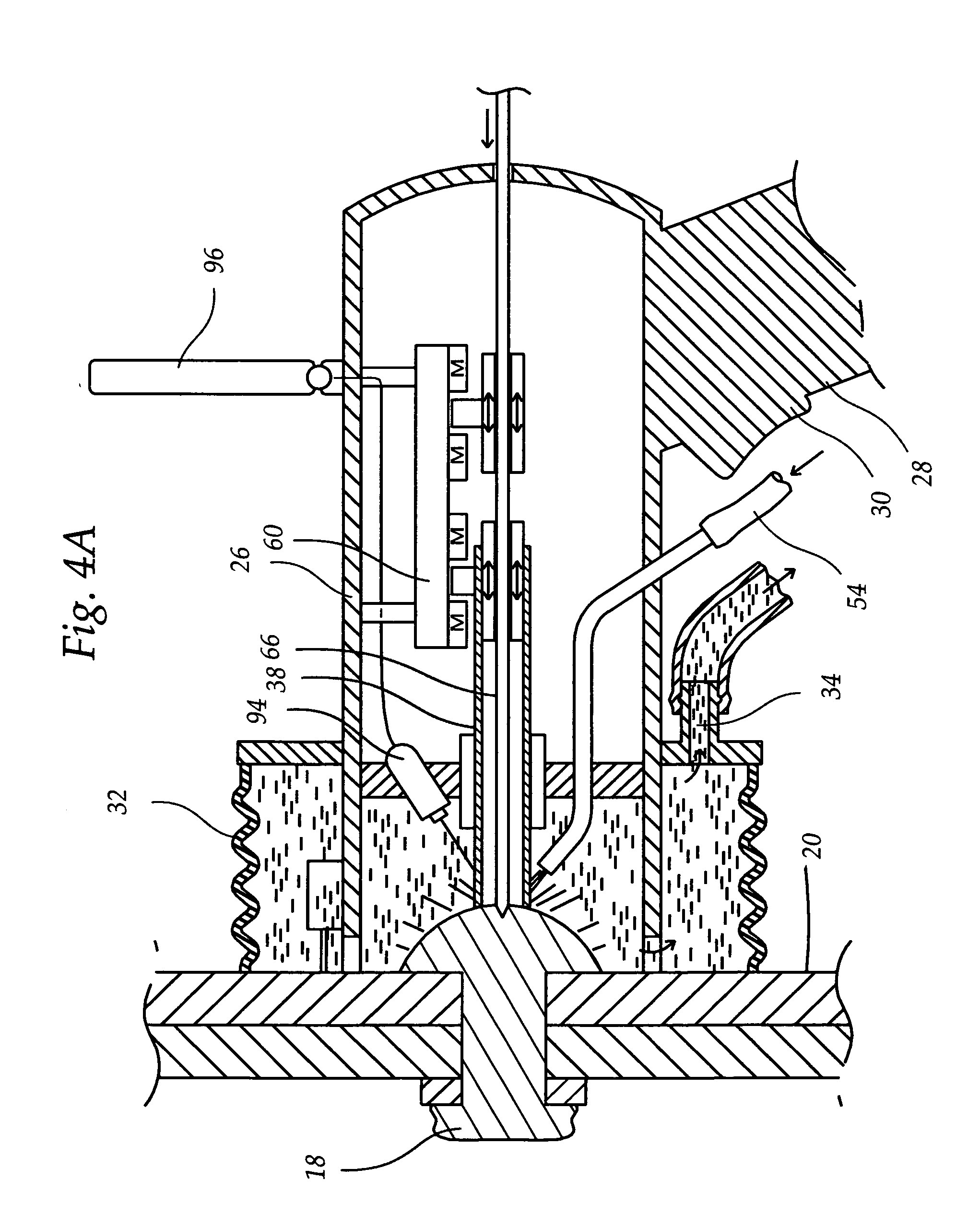
[0044]As shown in the figures, a hand-held device 10 may be positioned to remove a fastener 18 which extends through one or more frames. As further shown in the figures, fastener 18 and fastener collar 24 secure one or more frames. As will be clear to those skilled in the art, any variety of fasteners and associated components may be the object upon which some exemplary implementations of the disclosed device and met...


PUM

PropertyMeasurementUnit
shapeaaaaaaaaaa
outer diameteraaaaaaaaaa
diameteraaaaaaaaaa

Abstract

The hand-held electro-discharge device to remove boluses of material from a workpiece. In some implementations a conductive electrode and its supporting ground pin are immersed in a dielectric fluid contained in a hood or cavity near or at the electrode's distal tip an removably sealed to a conductive workpiece. A flushing inlet and outlet in fluid communication with said hood provide a flushing fluid, which may also be a dielectric fluid to remove FOD and cool.

Description

RELATED APPLICATION[0001]This application claims the full Paris Convention benefit of and priority to U.S. Provisional Patent Application Ser. No. 61 / 196,806, filed Oct. 21, 2008; is a continuation of U.S. patent application Ser. No. 12 / 603,507, filed Oct. 21, 2009; and PCT Patent Application No. PCT / US2009 / 061554, filed Oct. 21, 2009; the contents of which are incorporated by reference herein in their entirety, as if fully set forth herein.BACKGROUND[0002]1. Field[0003]This disclosure relates to flushing for erosion devices and processes.[0004]2. General Background[0005]Single-use fasteners, such as a rivet or aerospace fastener where the fastener is formed during the assembly process, is common in many industries. In aerospace, the maintenance of air frames frequently requires removal of hundreds of fasteners in order to replace or repair structural members such as longerons, bulkheads, center barrels, and the like. Fasteners commonly include rivets or threaded fasteners which hav...

Claims


Application Information

Patent Timeline
Patent Type & Authority Applications(United States)
IPC IPC(8): B23H1/00
CPCB23H1/00B23H1/04B23H9/001B23H7/26B23H1/10
Inventor GOLD, KENNETH STEWARTRUDGLEY, MERVYNGIBBONS, MICHAELLEGGE, JAMES T.GERLACH, RICHARD K.
Owner PERFECT POINT EDM CORP
Why Eureka
Try Eureka