Molding machine

a mold and machine body technology, applied in the field of molds, can solve the problems of low mold production efficiency, and achieve the effect of shortening the time required for mold formation and increasing production efficiency

Active Publication Date: 2012-08-28
SINTOKOGIO LTD
View PDF17 Cites 0 Cited by
  • Summary
  • Abstract
  • Description
  • Claims
  • Application Information

AI Technical Summary

Benefits of technology

[0004]Accordingly, this invention aims to provide a molding machine that can shorten the time required to form flaskless molds, and that can increase production efficiency.
[0005]The present invention provides a molding machine to mold a pair of flaskless molds. This molding machine comprises a first flask and a second flask; an exchangeable match plate having a first face and a second face corresponding to the first flask and the second flask, wherein the match plate is adapted to be held between the first flask and the second flask in a sandwich relationship; means for relatively moving either or both of the first flask and the second flask to the match plate such that the first and second flasks can hold and release the match plate therebetween; a first squeeze member having a first pressure-applying plane, wherein the first squeeze member is insertable into the first flask with the first pressure-applying plane being opposed to the first face of the match plate, and wherein the first squeeze member is inserted into the first flask when the first flask and the second flask hold the match plate in a sandwich relationship therebetween to define a first mold cavity by the first pressure-applying plane, the first face of the match plate, and the first flask; supporting means for supporting the first flask, the second flask, the match plate, and the first squeeze member, and for rotating them in unison between a horizontal position in which the first flask and the second flask hold the match plate therebetween in the sandwich relationship with the first pressure-applying plane of the first squeeze member being oriented vertically and downward, and a vertical position in which the first pressure-applying plane is oriented horizontally; a filling frame located to abut the second flask in a perpendicular position in the filling frame when the first and second flasks hold the match plate therebetween in the sandwich relationship at the vertical position; a second squeeze member having a second pressure-applying plane that is oriented horizontally, wherein the second squeeze member is insertable into the filling frame, and wherein the second squeeze member is insertable into the second flask through the filling frame when the first and second flasks hold the match plate therebetween with the second pressure-applying plane being opposed to the second face of the match plate at the vertical position to define a second mold cavity by the second pressure-applying plane, the second face of the match plate, the filling frame, and the second flask; a first actuator to move the first squeeze member to the first face of the match plate such that molding sand within the first mold cavity is squeezed by the first pressure-applying plane of the inserted first squeeze member; and a second actuator to move the second squeeze member to the second face of the match plate such that molding sand within the second mold cavity is squeezed by the second pressure-applying plane of the second squeeze member.

Problems solved by technology

Because this situation results in a molding cycle in the conventional flaskless molding machine that still requires much time, the production efficiency of molds is low.

Method used


Image

  • Molding machine
  • Molding machine
  • Molding machine

Examples


Embodiment Construction

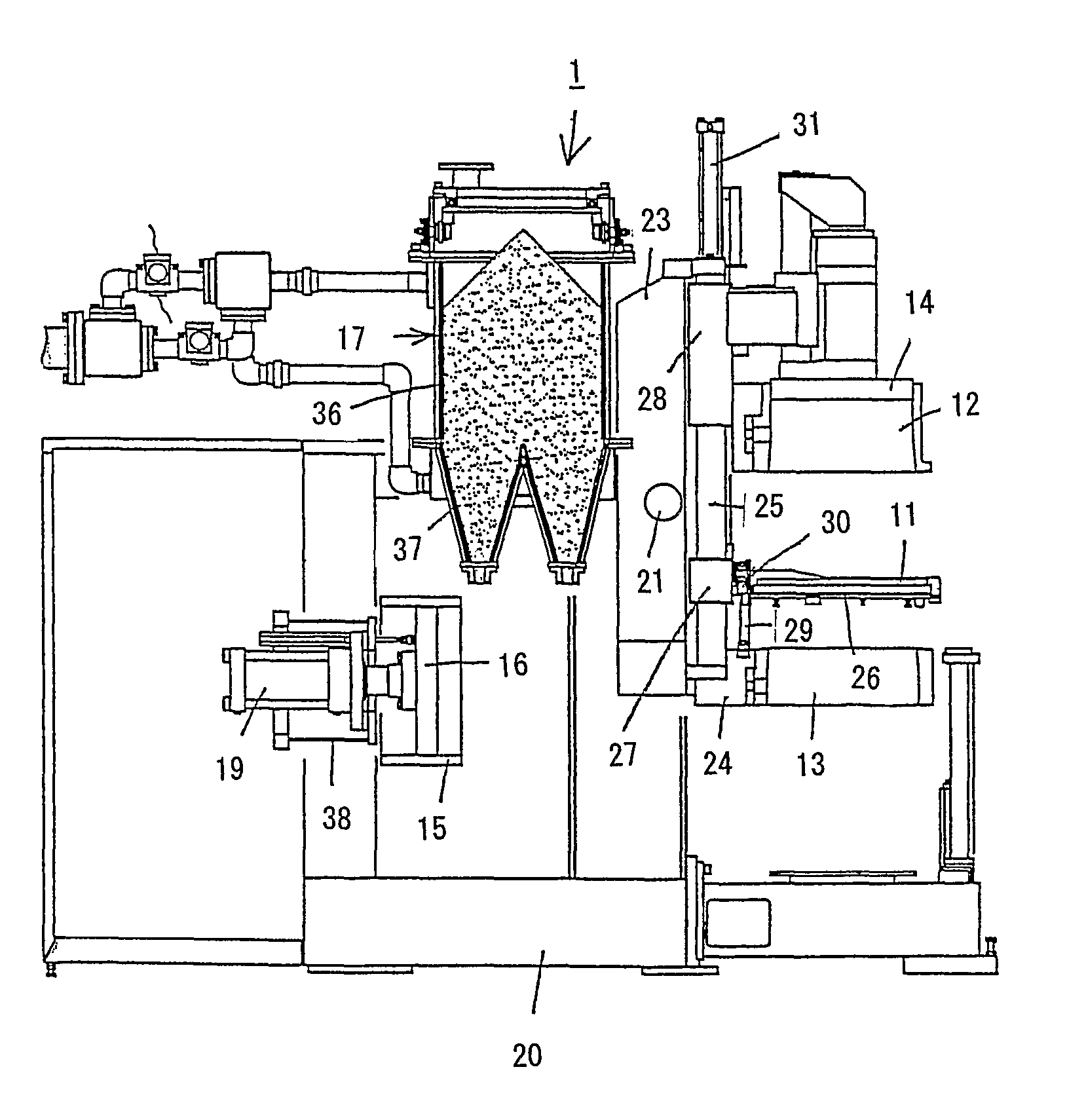
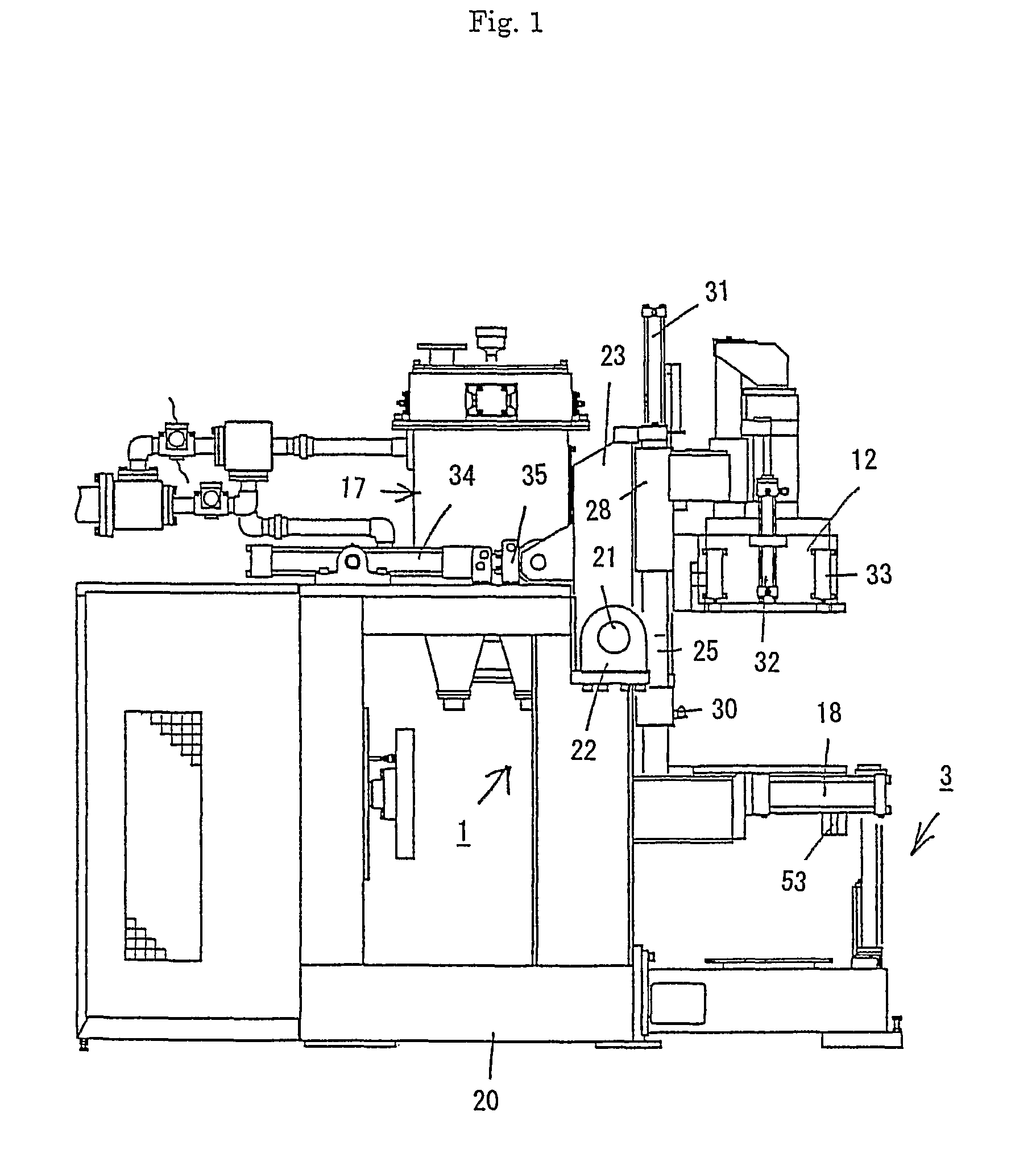
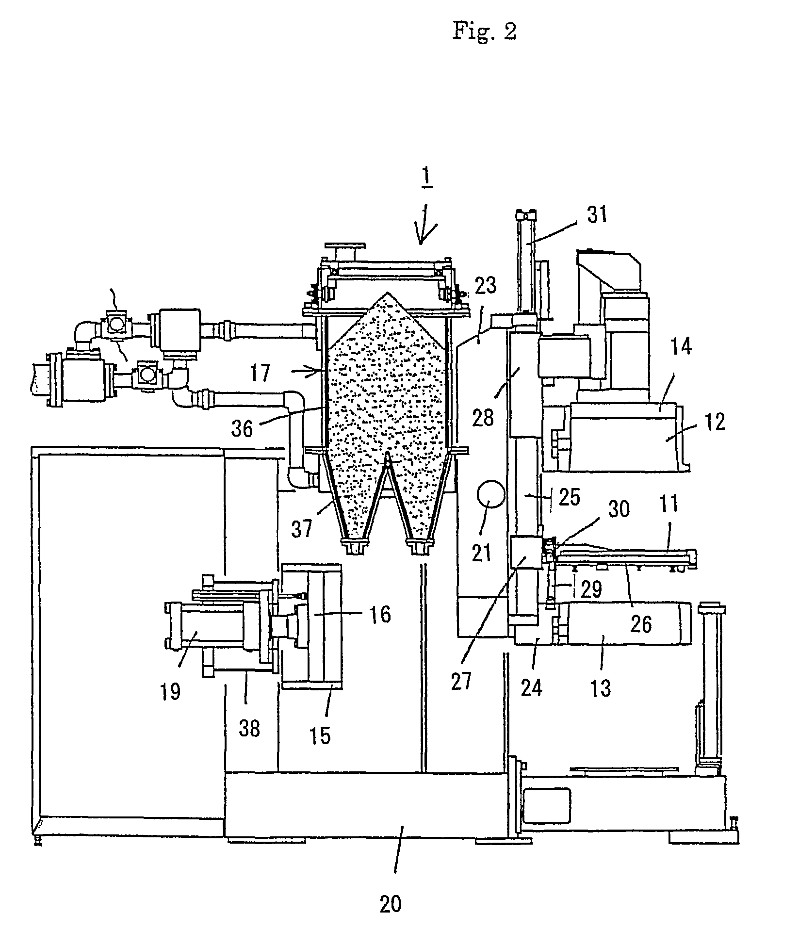
[0025]FIGS. 1 to 4 show one embodiment of the flaskless molding machine of the present invention. The flaskless molding machine generally includes a main unit 1 on a machinery mount 20 of the machine, a shuttle 2 (FIG. 3) for carrying in and carrying out a match plate 11 (FIG. 2) between an cope flask 12 and a drag flask 13 of the main unit 1, and a mold stripping equipment 3 for stripping the resulting upper and lower molds that are molded in the main unit 1 from the cope and the drag flasks 12 and 13. Both faces of the match plate 11 are mount with patterns.

[0026]1. Main Unit of Molding Machine

[0027]On the molding machine of the present invention, first the main unit 1 of it will be described. As is best shown in FIG. 2, the main unit 1 includes the cope flask (a first flask) 12 and the drag flask (a second flask) 13, which can clamp and hold the match plate 11 therebetween, an upper squeeze member 14 that is insertable in the cope flask to oppose the upper plane of the match plat...


PUM

PropertyMeasurementUnit
pressureaaaaaaaaaa
timeaaaaaaaaaa
moldingaaaaaaaaaa

Abstract

A molding machine that defines upper and lower mold cavities while cope and drag flasks, having a match plate sandwiched therebetween, are rotated from a horizontal position to a vertical position. An upper squeeze member is insertable into the cope flask. A pressure-applying plane of the upper squeeze member defines an upper mold cavity together with the match plate and the cope flask. A pivoting frame supports the cope and drag flasks, having a match plate sandwiched therebetween, and the upper squeeze member, such that they rotate in unison between a horizontal position to a vertical position. A fixed filling frame abuts the drag flask when the cope and drag flasks are in the vertical position. A lower squeeze member has a pressure-applying plane that is oriented horizontally. The pressure-applying plane of the lower squeeze member defines a lower mold cavity together with the match plate, the drag flask, and the filling frame.

Description

FIELD OF THE INVENTION[0001]This invention relates to a molding machine, more particularly, one to mold upper and drag flaskless molds at the same time.BACKGROUND OF THE INVENTION[0002]In the flaskless molding method, an attempt has been made to improve work efficiency by using a well-known flaskless molding machine. For example, Japanese Early-Patent Publication No. 04-66245 suggests that a well-known flaskless molding machine be combined with a pattern change device. The pattern exchanges mechanically and automatically, rather than manually, a used pattern plate that is used to form molds in the molding machine, for a new pattern plate.[0003]However, the flaskless molding machine employed as in the above disclosure is well known, and has also been used in a conventional flaskless molding method, where the pattern plates are exchanged manually. Therefore, this disclosure and the conventional flaskless molding method, where the pattern plates are manually exchanged, are the same as ...

Claims


Application Information

Patent Timeline
Patent Type & Authority Patents(United States)
IPC IPC(8): B22C17/12B22C17/08B22C15/28
CPCB22C11/10B22C15/28B22C17/08B22C17/10B22C17/12
Inventor HIRATA, MINORUKOMIYAMA, TAKAYUKIOYA, TOSHIHIKOSAKAI, TSUYOSHISAKAGUCHI, KOICHI
Owner SINTOKOGIO LTD
Why Eureka
Try Eureka