Terminal for connecting lead ends

a technology of terminals and leads, applied in the direction of coupling device details, coupling device connections, contact members penetrating/cutting insulation/cable strands, etc., can solve the problem of difficult to achieve good handling of the actuating element in the known terminals

Inactive Publication Date: 2012-08-28
WEIDMULLER INTERFACE GMBH & CO KG
View PDF9 Cites 64 Cited by
  • Summary
  • Abstract
  • Description
  • Claims
  • Application Information

AI Technical Summary

Benefits of technology

[0015]A particularly stable and compact configuration is achieved if the two actuating elements—preferably made of a synthetic plastic material—each act on one of the clamping springs, respectively, via a bracket arm—preferably consisting of metal.
[0018]According to another feature, the connecting device of this type is configured such that the clamping site can be closed by applying pressure to the conductor end in the conductor insertion direction, and opened again by applying pressure to the conductor end once again. Connecting and disconnecting operations are thus achieved by simple constructive means without the use of tools.

Problems solved by technology

However it is difficult in the known terminals to achieve good handling of the actuating element and, in particular, to achieve the opening position of the clamping spring with simple means in the disconnected state of the terminal, i.e. without a conductor, in which position a conductor can easily be inserted into, or removed from, the clamping site.

Method used


Image

  • Terminal for connecting lead ends
  • Terminal for connecting lead ends
  • Terminal for connecting lead ends

Examples


Embodiment Construction

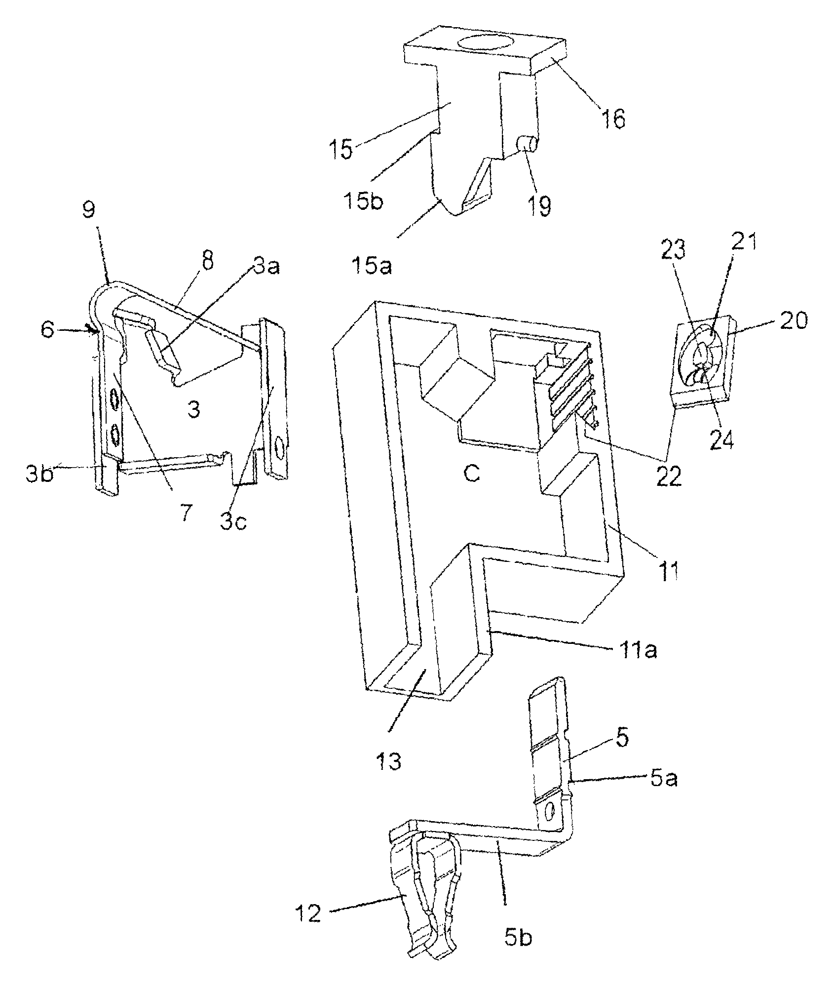
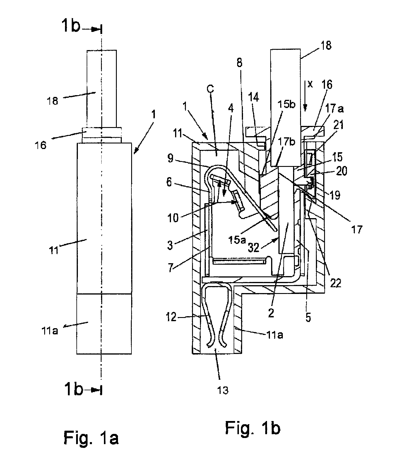
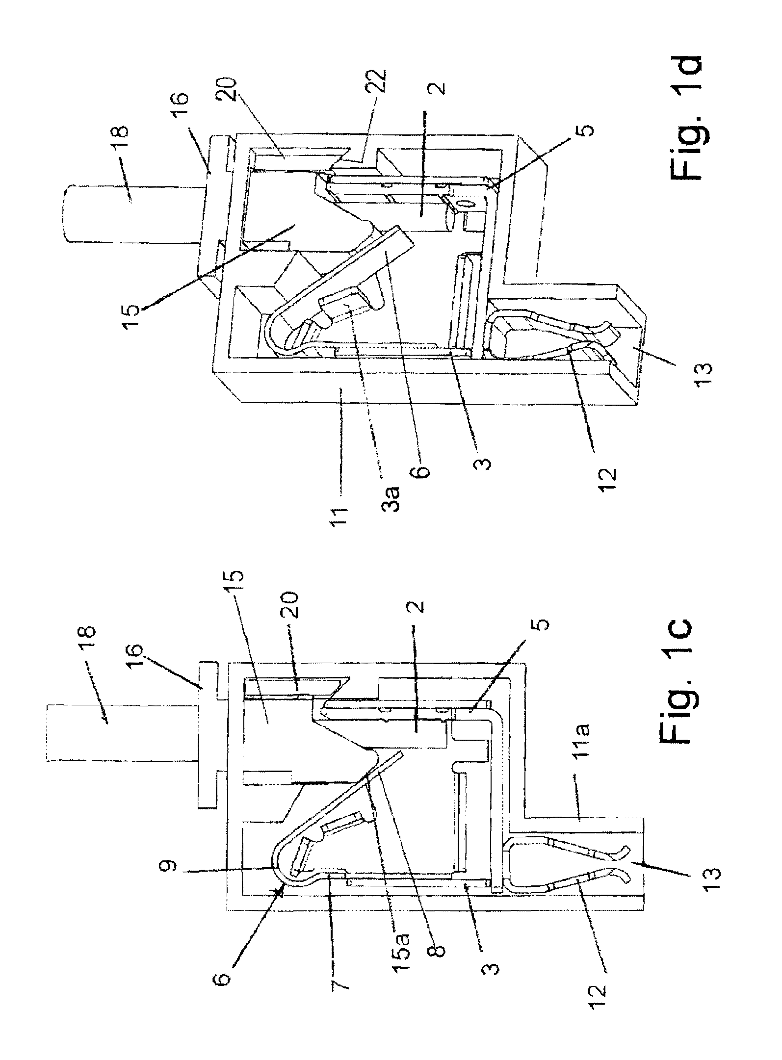
[0030]Referring first more particularly to FIGS. 1b and 5, the electrical connector 1 includes a rectangular housing 11 formed of electrically insulating synthetic plastic material and containing a chamber C. Mounted for vertical sliding displacement in an opening 14 contained in the housing top wall is an operating member 15 having a top flange portion 16, and an inclined bottom surface 15a. A projection 19 defining a cam follower extends rigidly from one side wall of the operating member, and a stop surface 15b is defined by an abutment on the opposite side wall. As shown in FIG. 1b, the operating member contains a vertical through bore 17 having at its upper end a counterbore 17a that defines a bottom wall 17b.

[0031]Mounted in the housing chamber C is a bent sheet metal cage 3 having a first orthogonally bent stop flange 3a, and a pair of orthogonally bent parallel support flanges 3b and 3c. Secured to cage support flange 3b is one leg 7 of an inverted V-shaped leaf spring 6. Th...


PUM


Abstract

An electrical connector for connecting the bare end of an insulated conductor with an electrical contact, including a connector housing containing a chamber in which are mounted a bus bar connected with the contact, and a clamping spring normally biased toward the bus bar. A retaining device maintains the spring in a retained open condition spaced from said bus bar, thereby to permit the conductor bare end to be introduced into the chamber toward a clamping position adjacent the bus bar. An operating member is displaced in a controlled manner to release the spring from its retained condition, whereby the spring biases the conductor toward electrical engagement with the bus bar. To remove the conductor, the operating member is operated again to displace the spring toward its open condition.

Description

REFERENCE TO RELATED APPLICATIONS[0001]This application is a 371 of PCT / EP2009 / 061535 filed Sep. 7, 2009, claiming priority of German Application No. DE 20 2008 014 469.8 filed Oct. 31, 2008.BACKGROUND OF THE INVENTION[0002]1. Field of the Invention[0003]An electrical connector for connecting the bare end of an insulated conductor with an electrical contact, including a connector housing containing a chamber in which are mounted a bus bar connected with the contact, and a clamping spring normally biased toward the bus bar. A retaining arrangement maintains the spring in a retained open condition spaced from said bus bar, thereby to permit the conductor bare end to be introduced into the chamber toward a clamping position adjacent the bus bar. An operating member releases the spring from its retained condition, whereby the spring biases the conductor toward electrical engagement with the bus bar.[0004]2. Description of Related Art[0005]It is well known in the prior art to provide ele...

Claims


Application Information

Patent Timeline
Patent Type & Authority Patents(United States)
IPC IPC(8): H01R11/20
CPCH01R4/4836H01R4/48365
Inventor HECKERT, MICHAELLANG, THOMAS
Owner WEIDMULLER INTERFACE GMBH & CO KG
Why Eureka
Try Eureka