
Tank

a tank and tank body technology, applied in the field of tanks, can solve the problems of machine control not being able to initiate the intended maintenance interval, problems such as warranty questions, not only in terms of machine operation reliability, etc., and achieve the effect of improving operation

Active Publication Date: 2012-08-28
AQUIS WASSER LUFT SYST GMBH LINDAU ZWEIGNIEDERLASSUNG REBSTEIN
View PDF34 Cites 0 Cited by
  • Summary
  • Abstract
  • Description
  • Claims
  • Application Information

AI Technical Summary

Benefits of technology

[0009]Correspondingly, a tank according to the invention with a suction connection element for sucking in water from the tank by means of a vacuum and with a filter connection for connecting a filter cartridge inside and / or outside the tank, is distinguished in that a blending device or blend setting is provided, by means of which a bypass stream of unfiltered or otherwise treated water is routed past the filter bed. As a result, the quality of the water supplied to a water-treating and / or water-consuming appliance can be set, for example specifically to the application and / or to the appliance, by mixing the water filtered by the filter cartridge and the water not filtered by it or by mixing the water filtered by one filter stage with water filtered by one or more other filter stages. Furthermore, the operational running time can thus be optimized in that the filter does not have to be exchanged sooner than is the case when a water quality sufficient for the respective application is provided as a result of the exhaustion of the filter material. If a comparatively smaller quantity of water is passed through by virtue of the blending according to the invention of the water to be filtered, therefore, the filter material used for this purpose can thus be available for longer because of its consequently lower degree of exhaustion over time.
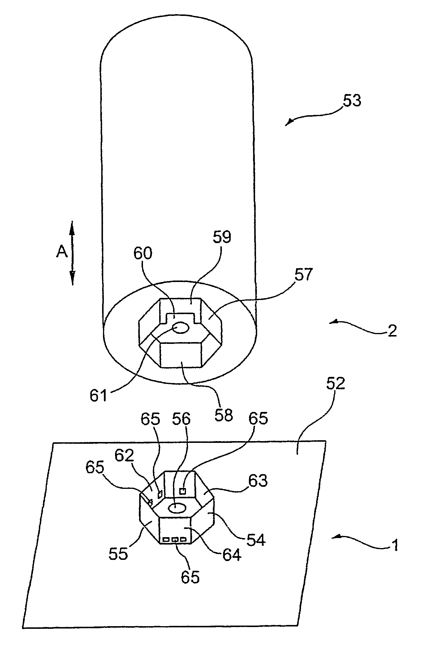
[0043]A further possibility for coding the tank / filter connection is to vary the orientation of the longitudinal axis running through the filter-side tank connection element with respect to a longitudinal axis running through the filter housing, so that these form, for example, a specific, in particular acute angle to one another. For this purpose, the filter-side tank connection element may be designed to be preferably slightly bent with respect to the cartridge housing. Cartridges which have no connection element with such a bent orientation in position cannot be inserted operably in a water tank of correspondingly narrow design. A further advantage of such coding is that even curved and / or arcuately designed water tanks of comparatively long longitudinal extent can be equipped in an operationally safe manner and reliably, since, by virtue of the angling of the two longitudinal axes with respect to one another, a correspondingly reliably sealing and fixing tank / filter receptacle can be implemented by means of an optimal orientation of the tank-side filter connection element in the tank and by an insertion movement for the angular cartridge which deviates from a vertical introduction movement.

Problems solved by technology

If a filter cartridge is defective, the machine is supplied with insufficiently or wrongly treated water, and this may lead to adverse effects, for example calcification or the like, even amounting to machine defects.
The machine control is not capable of initiating the intended maintenance intervals in due time if it is based on a filter cartridge of the correct type, but this is not actually used.
If inadequate filter cartridges are used, problems arise not only in terms of the operating reliability of the machine, but also with regard to warranty questions, etc.

Method used


Image

  • Tank
  • Tank
  • Tank

Examples


Embodiment Construction

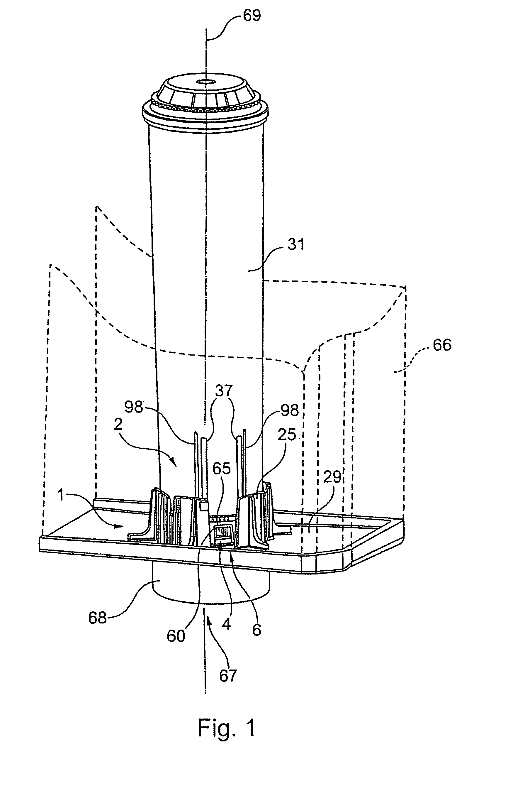
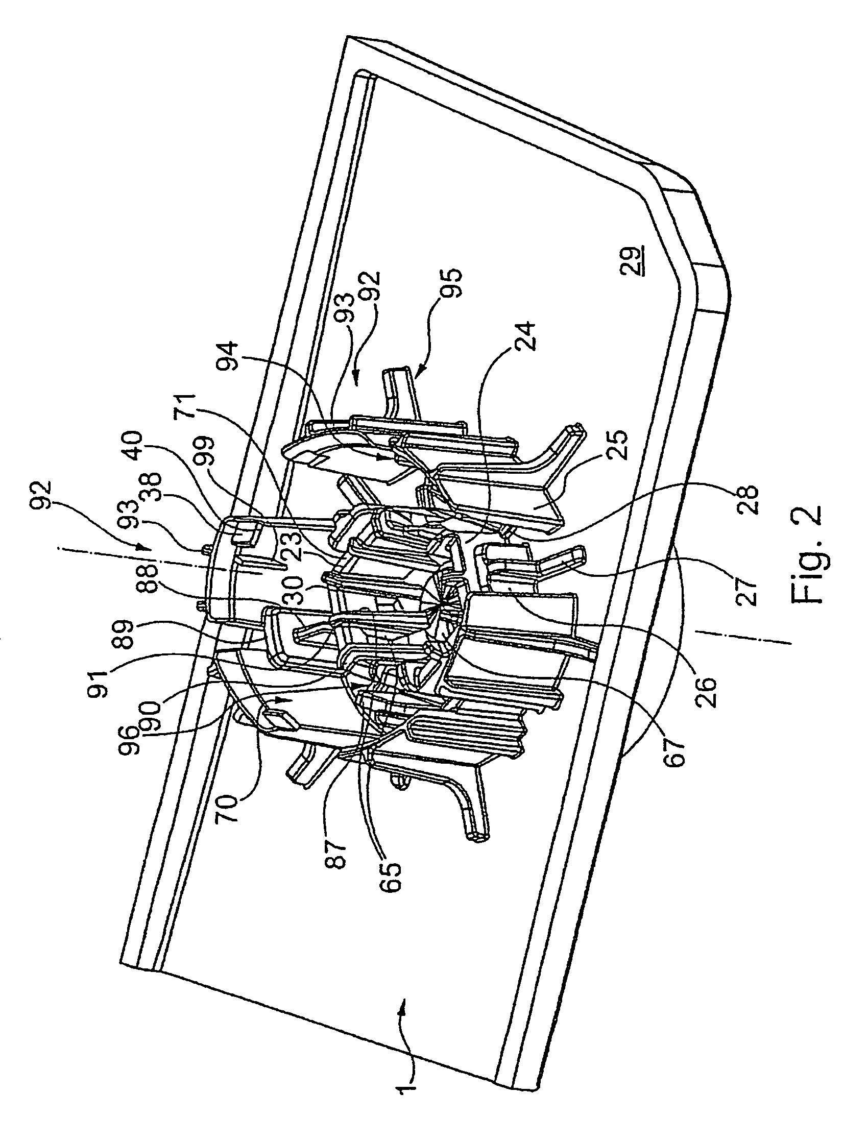
[0060]FIG. 1 shows connection elements 1, 2 of a tank 66, illustrated diagrammatically in cutout form by dashed lines, and of an associated filter cartridge 31. Illustrated on the tank side is a connecting socket 1 which is connected, for example welded, adhesively bonded or otherwise fastened, fixedly to the bottom 29 of the associated tank 66. The tank connection element 2 of the filter cartridge 31 is inserted into this connecting socket 1. The filter-side tank connection element 2 can be seen more clearly in FIG. 4 and comprises a connection piece 4 which merges into the cartridge housing 36. In the design variant according to FIGS. 1 and 4, the water to be filtered passes via lateral slots 6 and subsequently via passage ports 34 arranged on the cartridge bottom side into the interior of the cartridge housing 36 and thereafter passes through a filter bed, not illustrated in any more detail. The filter zone may in this case be formed in the up flow, in the down flow or in combina...


PUM

PropertyMeasurementUnit
angleaaaaaaaaaa
coding structuresaaaaaaaaaa
structureaaaaaaaaaa

Abstract

A tank for water-carrying appliances is proposed, in particular domestic appliances or appliances for the treatment of foods and / or beverages, such as beverage vending machines, in particular coffee vending machines, drinking water dispensers, cooking and baking appliances, steam appliances, in particular steam irons, steam cleaners, high-pressure cleaners, air purifiers and conditioners or the like, a suction connection on the tank for the intake of water from the tank, with means for generating a vacuum, and a filter connection for connecting a filter cartridge inside the tank being provided, while it is ensured that only one permitted filter type is used. A tank according to the invention is characterized by mechanical coding structures at the filter connection element in order to exclude the use of a filter cartridge which does not correspond to the tank.

Description

CROSS REFERENCE TO RELATED APPLICATIONS[0001]The subject matter of this application is related to the subject matter of U.S. application Ser. No. 12 / 310,062 filed Feb. 10, 2009; U.S. application Ser. No. 12 / 310,071 filed Feb. 10, 2009; U.S. application Ser. No. 12 / 310,072 filed Feb. 10, 2009 and U.S. application Ser. No. 12 / 310,037 filed Apr. 23, 2009.BACKGROUND OF THE INVENTION[0002](1) Field of the Invention[0003]The invention relates to a tank with a filter cartridge for water dispensing appliances, particularly domestic appliances such as beverage vending machines including coffee vending machines, drinking water dispensers, cooking and baking appliances, steam appliances such as steam irons, steam cleaners, high-pressure cleaners, air purifiers and conditioners or the like and particularly those appliances having a suction connection on the tank for the intake of water from the water tank with a vacuum generating device which has a filter connection and a filter disposed inside...

Claims


Application Information

Patent Timeline
Patent Type & Authority Patents(United States)
IPC IPC(8): B01D35/30B01D24/00
CPCA47J31/605C02F1/003B01D2201/4023B01D2201/4046B01D2201/4015C02F1/283C02F2201/006C02F2301/043B01D27/08A47J31/44
Inventor WALLERSTORFER, KURTWAWRLA, ANDREASSCHOLZ, ROLAND
Owner AQUIS WASSER LUFT SYST GMBH LINDAU ZWEIGNIEDERLASSUNG REBSTEIN
Learn More