CMC wall structure with integral cooling channels

Active Publication Date: 2012-09-04
SIEMENS ENERGY INC
View PDF16 Cites 48 Cited by
  • Summary
  • Abstract
  • Description
  • Claims
  • Application Information

AI Technical Summary

Problems solved by technology

Current materials of this type provide strength and temperature stability to temperatures approaching 1700° C. Cooling of such structures is generally limited to back side air impingement cooling.

Method used


Image

  • CMC wall structure with integral cooling channels
  • CMC wall structure with integral cooling channels
  • CMC wall structure with integral cooling channels

Examples


Embodiment Construction

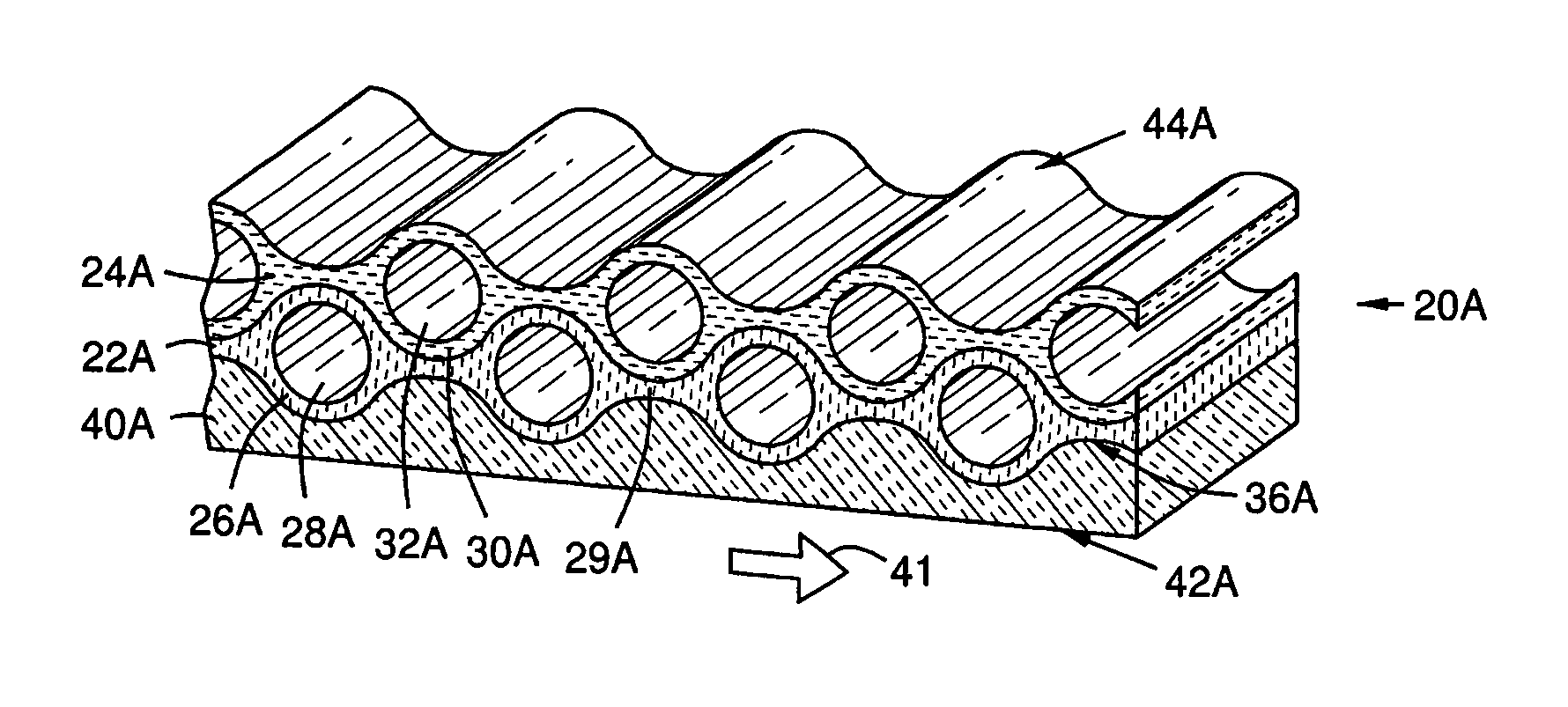
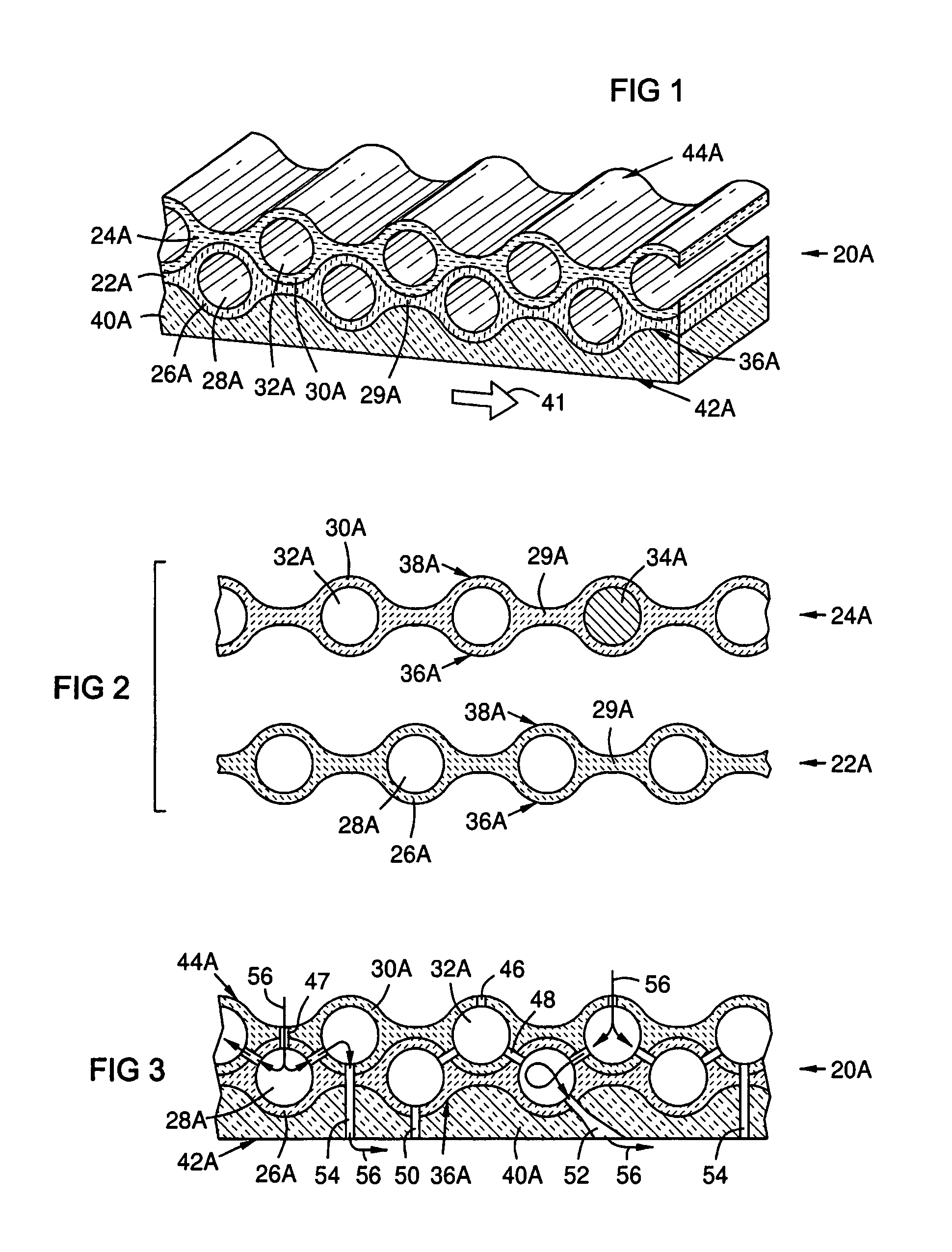
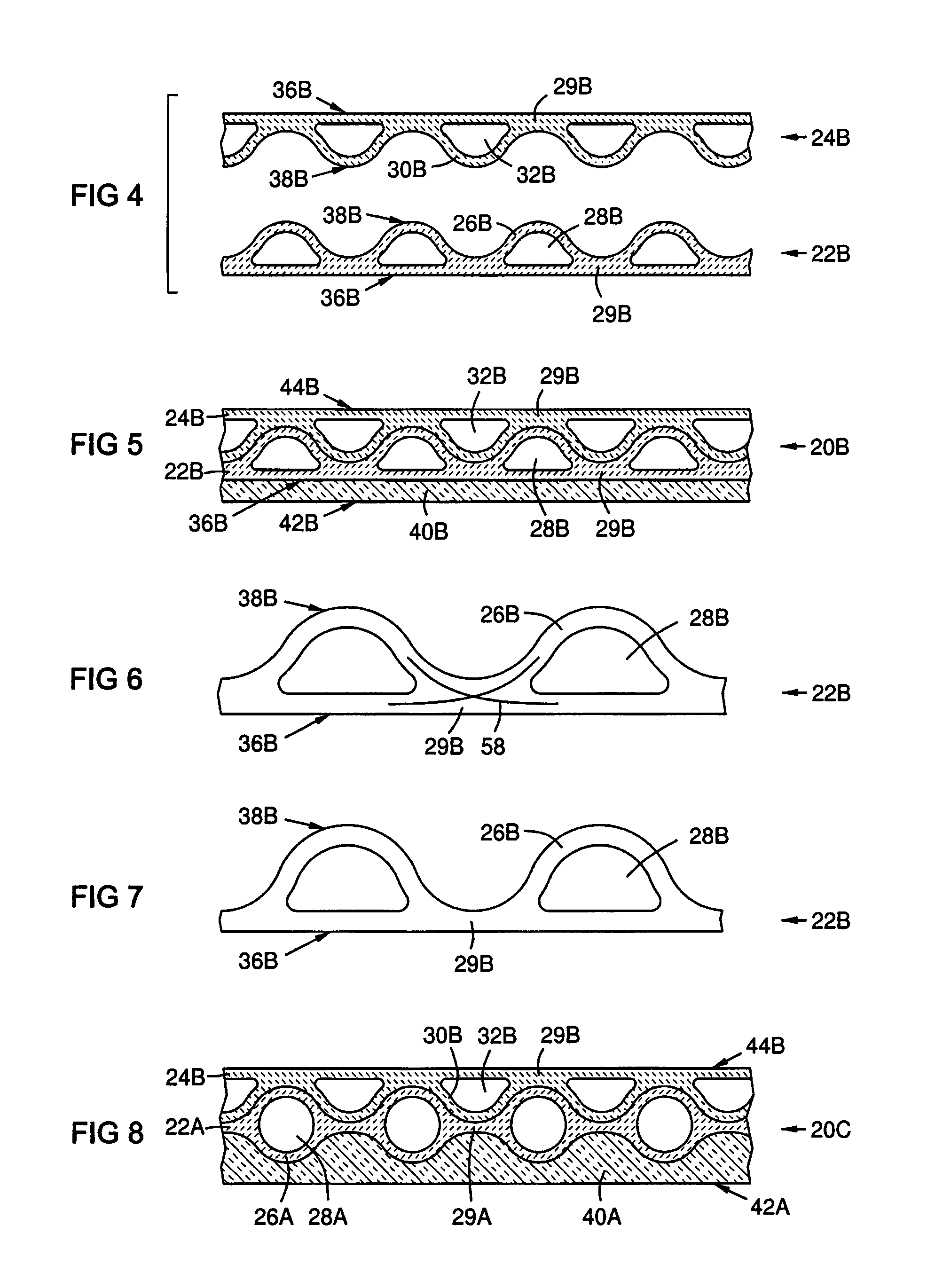
[0013]The present inventors have found that existing 2D laminate CMC structures are sometimes limited by their relatively low interlaminar strength. An increase in the thickness of the CMC structure will often compensate for relatively low interlaminar strength, however, an increased thickness increases cost, size and weight and reduces the effectiveness of backside cooling. Three dimensional CMC architectures may be used; however, the present inventors have also found that 3D architecture preforms that are significantly greater in thickness than a single fabric ply cannot be infiltrated readily with current matrix infiltration methods. The CMC wall structure geometry of the present invention provides improved performance in interlaminar strength while also providing a means for effective matrix infiltration.

[0014]FIG. 1 is a sectional view of a first of three embodiments of the present invention that are described herein. Reference numerals used to describe features illustrated in ...


PUM

PropertyMeasurementUnit
temperaturesaaaaaaaaaa
interlaminar strengthsaaaaaaaaaa
temperatureaaaaaaaaaa

Abstract

A ceramic matrix composite wall structure (20A) constructed of interlocking layers (22A, 24A) of woven material with integral cooling channels (28A, 32A). The CMC layer closest to the hot gas path (41) contains internal cooling tubes (26A, 30A) protruding into a ceramic insulating layer (40A). This construction provides a cooled CMC lamellate wall structure with an interlocking truss core.

Description

FIELD OF THE INVENTION[0001]The invention relates generally to ceramic matrix composites (CMC), and more particularly to a cooled CMC wall structure suitable for fabrication with oxide-oxide CMC materials.BACKGROUND OF THE INVENTION[0002]Engine components exposed to the hot combustion gas flow of combustion turbine engines may be formed of a ceramic refractory material. A ceramic matrix composite (CMC) lamellate wall structure with a high temperature ceramic insulation coating, commonly referred to as friable grade insulation (FGI), is described in commonly assigned U.S. Pat. No. 6,197,424. Current materials of this type provide strength and temperature stability to temperatures approaching 1700° C. Cooling of such structures is generally limited to back side air impingement cooling.[0003]Future combustion turbine designs are expected to require ever increasing firing temperatures that may exceed the operating limits of such designs. An actively cooled CMC wall structure is describe...

Claims


Application Information

Patent Timeline
Patent Type & Authority Patents(United States)
IPC IPC(8): B32B1/08B32B3/00B32B3/20D03D11/00
CPCB32B18/00F01D5/282F28F7/02F28F21/04C04B35/803C04B37/001F01D5/187Y10T428/1314C04B2237/34C04B2237/38C04B2237/62F05D2260/201C04B2237/64Y10T428/1393Y10T428/139Y10T428/24612Y10T428/1362Y10T428/24521Y10T428/24744Y10T428/1317Y10T428/131Y10T442/3195Y10T442/3203Y10T442/3211C04B35/01C04B2235/522C04B2235/5252C04B35/80
Inventor MORRISON, JAY A.KELLER, DOUGLAS A.GONZALEZ, MALBERTO F.LANE, JAY E.
Owner SIEMENS ENERGY INC
Why Eureka
Try Eureka