Stator arrangement for an electric motor

a technology of electric motors and stator bodies, which is applied in the direction of dynamo-electric machines, electrical devices, windings, etc., can solve the problems of inability to achieve the effect of a single unit, serious malfunctions, and total failure of the motor, and achieve the effect of convenient and fast assembly

Active Publication Date: 2012-09-04
EBM PAPST MULFINGEN GMBH & CO KG
View PDF13 Cites 9 Cited by
  • Summary
  • Abstract
  • Description
  • Claims
  • Application Information

AI Technical Summary

Benefits of technology

[0004]According to the principles of the present invention, a stator arrangement is provided with a temperature monitor and can be easily and quickly assembled, and provides increased safety against temperature-induced malfunctions and damage.
[0005]Accordingly, it is provided according to the present invention that the temperature monitor is seated in a holding pocket that is connected resiliently and movably to the switching disk in such a manner that it (the temperature monitor) is located, via the holding pocket, in one of the stator grooves and comes into contact with the stator winding under the effect of a resilient pretension or biasing force. The holding pocket is matched in shape to the groove and winding geometry in such a manner that it engages axially and relatively far (deeply) into the stator groove and can tightly contact (adapt to) the winding with a defined pressing force over a large area, due to its spring-elastic mobility. The temperature monitor is inserted into the holding pocket with zero clearance in a force fitting manner so that it is tightly seated in the holding pocket, almost without an air gap. At least on the side of the holding pocket facing the respective stator winding, the holding pocket has a wall formed sufficiently thin such that the temperature monitor indirectly comes into thermally conductive surface contact with the stator winding.
[0006]Due to the spring-elastic mobility of the temperature monitor seated in the holding pocket, a required minimum contact force on the stator winding is always assured, compensating for manufacturing tolerances, which leads to optimal heat transfer. In addition, the heat detection inside the stator groove is particularly secure, in contrast to the detection on the winding overhang, so that increased safety is guaranteed due to reliable shutdown of the stator arrangement in case of overheating.
[0007]The holding pocket is preferably constructed of an electrically insulating plastic material. By forming at least the pocket wall that comes into contact with the stator winding very thinly, e.g., with a thickness of only a few tenths of a millimeter (in particular, approximately 0.4 mm), sufficiently good heat transfer between the winding and the temperature monitor is made possible, despite the use of plastic for the holding pocket. Due to its arrangement in the electrically insulating housing pocket, an inexpensive design can advantageously be used for the temperature monitor, e.g., a design without an external insulation of its own. Moreover, the temperature monitor can have a very compact, especially thin overall shape, so that even with a high degree of filling of the groove by the windings, it can be accommodated in the remaining free space of the stator groove by means of the correspondingly narrow holding pocket.
[0009]In another advantageous embodiment, all the holding pockets are integrally connected to a common carrier part, and thus indirectly fixed to the switching disk by means of the carrier part. For this purpose, the carrier part is connected, or can be connected, to the switching disk, on the side of the switching disk facing the stator winding overhang, by means of snap-fit connections. Each holding pocket is preferably integrally and resiliently connected to the carrier part via a connecting web in the peripheral area of an insertion opening through which the temperature monitor is received. In addition, the carrier part advantageously also has fixation means for electrical connection lines / wires of the temperature monitor, as well as, in particular, electrical plug connectors. In this advantageous embodiment, the carrier part with the temperature monitors forms a fully preassembled and pre-wired module that need merely be snapped into the switching disk for fixation. This leads to an extremely easy and fast assembly by avoiding the expense of manual individual wiring of the temperature monitors. The plug connectors on the carrier part make the electrical connection to an electronics unit.

Problems solved by technology

This is often not accomplished in practice because, due to manufacturing tolerances, there can be an undefined contact between the temperature monitor and the winding, or even an air gap between these two elements.
Therefore, serious malfunctions, or even a total failure of the motor, can occur due to inaccurate temperature detection.
Moreover, the temperature monitor / monitors must frequently be manually wired, which leads to expensive manufacturing costs.

Method used


Image

  • Stator arrangement for an electric motor
  • Stator arrangement for an electric motor
  • Stator arrangement for an electric motor

Examples


Embodiment Construction

[0020]In the various figures of the drawings, identical parts are always provided with identical reference numerals, so that only a single description of a part also applies analogously to other figures of the drawings in which the corresponding part can likewise be recognized by the corresponding reference numeral.

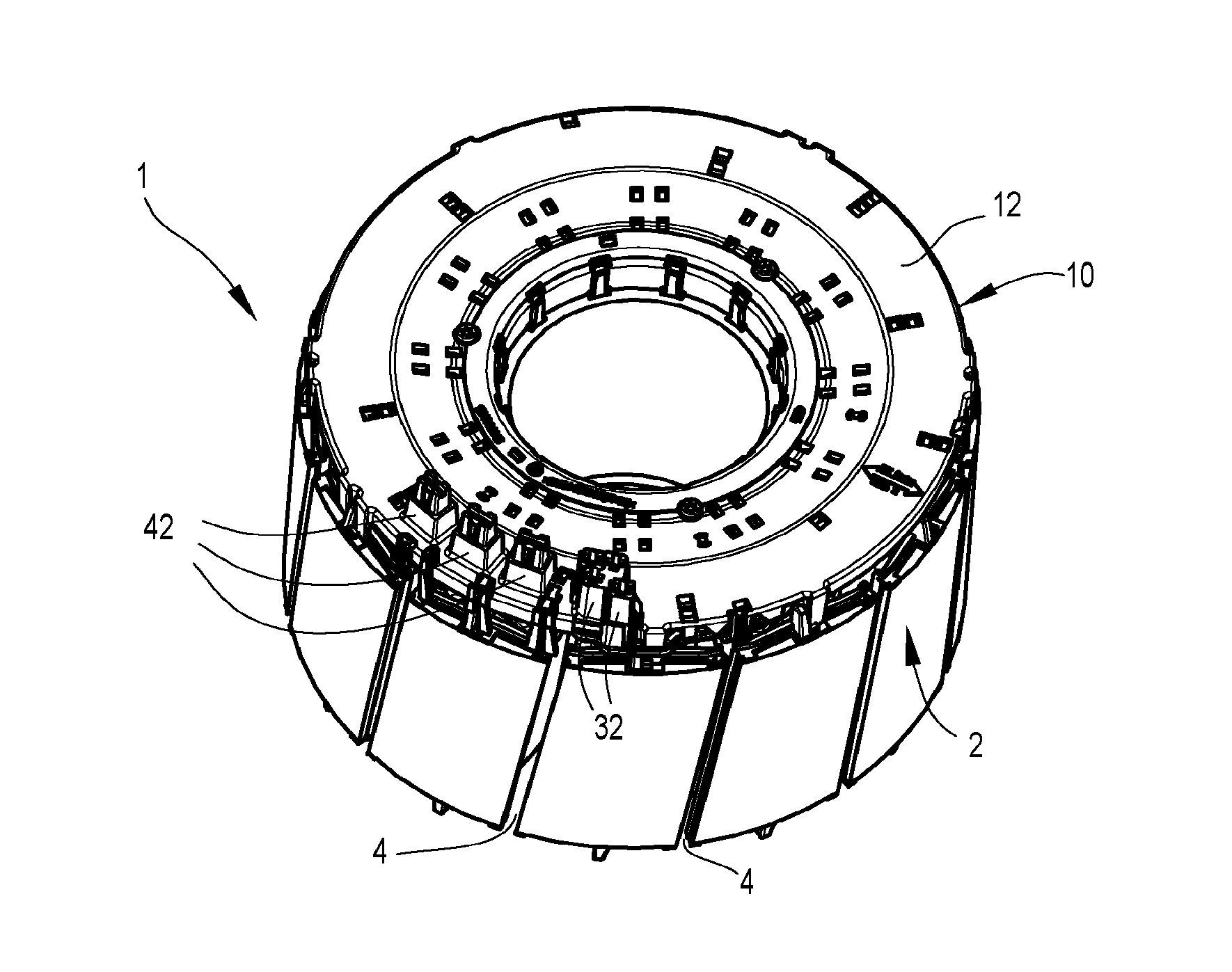
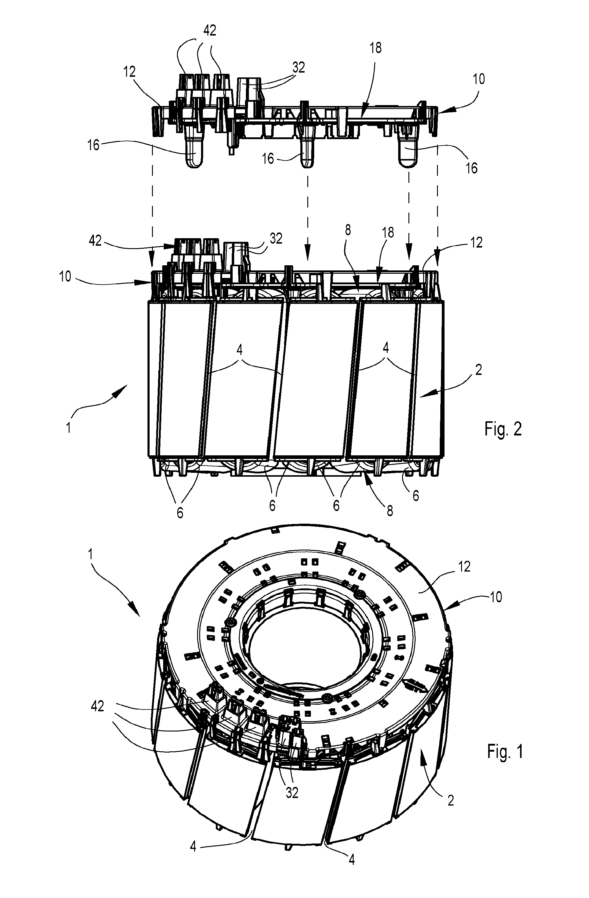
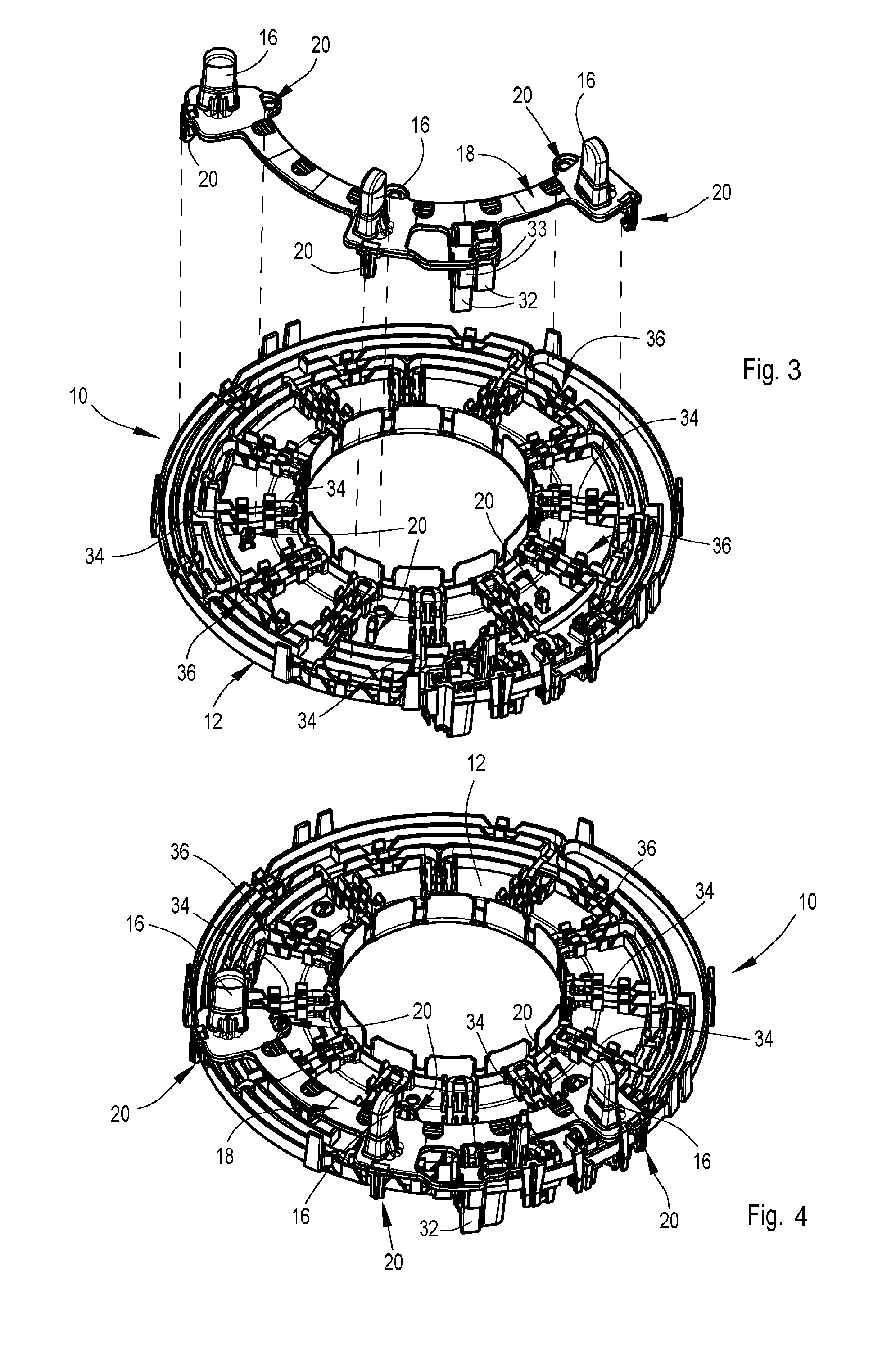
[0021]A stator arrangement 1, according to the present invention, principally includes a laminated stator core 2 with stator windings 6 running through stator grooves 4. The stator windings 6 run outside the stator grooves 4 in the area of the end faces of the laminated stator core 2, going from one groove to the next groove, and form winding overhangs 8 on each end face of the core 2. The stator arrangement 1 further has an interconnection unit 10 for electrically connecting the stator windings 6 to one another and to electric supply lines (not shown). The interconnection device 10 essentially consists of a circular or annular switching disk 12 lying in a plane perpendic...


PUM


Abstract

A stator arrangement for an electric motor. The stator arrangement including a laminated stator core with stator windings running through stator grooves and forming winding overhangs at each end face of the laminated stator core. The stator arrangement also includes an interconnection unit having a switching disk covering the winding overhangs on one end face of the stator. The switching disk further including at least one temperature monitor mounted thereon for monitoring the temperature of the stator windings. The temperature monitor being seated in a holding pocket that is resiliently connected to the switching disk in such a manner that, when positioned in one of the stator grooves, it is resiliently biased into engagement with a stator winding.

Description

BACKGROUND[0001]The present invention relates to a stator arrangement for an electric motor. More particularly, the invention relates to a stator arrangement having a temperature monitor that is provided so as to monitor the temperature of a stator winding in the stator arrangement.[0002]An electric motor with a stator arrangement is described in the document EP 2043234 A1. The unit consists of a laminated stator core wound with the stator windings. A switching disk covers a winding overhang and is connected to the motor electronics during assembly of the motor by axial joining via electrical plug connections. On the side facing the winding overhang, the switching disk includes at least one so-called temperature monitor that is intended to detect the respective stator temperature in order to effect a shut-off of the motor or the stator windings in case of overheating of the stator windings due to a malfunction.[0003]In known electric motors, the temperature monitor is typically arra...

Claims


Application Information

Patent Timeline
Patent Type & Authority Patents(United States)
IPC IPC(8): H02K11/00
CPCH02K11/0047H02K11/25H02K3/50H02K2203/09
Inventor STROBEL, OTHMARBEST, DIETER
Owner EBM PAPST MULFINGEN GMBH & CO KG
Why Eureka
Try Eureka