Image display device for an autostereoscopic display with a sweet spot unit containing an image matrix and a corrective matrix for correcting field curvature

Inactive Publication Date: 2012-09-04
SEEREAL TECHNOLOGIES
View PDF20 Cites 6 Cited by
  • Summary
  • Abstract
  • Description
  • Claims
  • Application Information

AI Technical Summary

Benefits of technology

[0025]An advantage of the invention is that only shape and pitch of the imaging and correction elements are matched, independent of the structure of the illumination matrix and image matrix. This provides the possibility to use various image matrix and illumination matrix structures without any adaptation when making a display device for an existing imaging matrix structure.
[0026]To correct the field curvature, a single corrective matrix is preferably disposed in the optical path of the imaging matrix.
[0027]In order to avoid the occurrence of disturbing reflections due to jumps in the refractive index in the imaging of the point elements, the refractive index of the corrective matrix is matched with that of the neighbouring medium, according to the position of the corrective matrix in the optical path.
[0028]In a preferred embodiment of the invention as an autostereoscopic multi-user display with a directed backlight, the point elements, which are arranged in a matrix, are controllable illumination elements of an illumination matrix, which are imaged on to the eyes of at least one viewer through a imaging matrix.
[0029]The illumination matrix may contain active illumination elements, such as LEDs or OLEDs, as well as passive illumination elements, such as pixels or sub-pixels of an illuminated LC-display. The controllable illumination elements can be, e.g., any defined number of openings of a shutter, each of said openings being assigned to one element of an imaging matrix and of a corrective matrix. This means that each imaging element and correction element, respectively, images an assigned number of pixels of the illumination matrix into the viewing space.
[0030]If the imaging matrix, e.g., is a lenticular of parallel arranged convex lenticules, the corrective matrix is a lenticular of parallel concave lenticules. The corrective matrix is preferably disposed near the illumination matrix or even connected to it with its planar face.

Problems solved by technology

This in turn leads to inhomogeneities within a sweet spot and cross-talk among sweet spots.
Controllable viewing angles, which can be realised with known sweet spot units, are therefore limited, in particular in a multi-user mode.
The image quality in the aforementioned image display devices may be deteriorated considerably by optical imaging errors of individual imaging elements of the imaging matrices.
In addition to spherical aberration, coma, distortion and Moiré effect, which is characteristic for combinations of periodic structures, e.g. of illumination and imaging matrix, particularly field curvature for large angles of light incidence is an adverse effect.
This causes cross-talk if the angles are sufficiently large.
The field curvature is a long time known optical imaging error also with parallel optical systems, i.e. imaging matrices, which occurs in the region of the individual imaging elements, adversely affecting the imaging behaviour of the respective optical device.
However, such a three-dimensional illumination matrix with complicated shape can only be realised with great efforts.
Moreover, this solution has the disadvantage that the shape of the illumination matrix must always be adapted to the imaging matrix used.
However, their application in the optical devices described above, i.e. with large viewing angles, is problematic.
Due to the spatial arrangement of individual lens elements there are gaps which may lead to vignetting.
But, in particular, multi-user displays require large viewing angles.
Thus, generally, the applicability of such lens arrays in autostereoscopic displays is limited.
Moreover, the manufacturing technology is rather expensive due to the multisectional arrangement of the lenticules or lenses.
The disadvantages of this solution are that despite expensive manufacture of the micro-lens arrays only small angular variations are possible, and that the brightness is reduced.
Drawbacks of this arrangement are the enormous efforts required for precise manufacture of the many micro-lenses and their accurate positioning on the three two-dimensionally curved faces, and the voluminous design of the entire device.
This solution is thus unsuitable in conjunction with the present application.

Method used


Image

  • Image display device for an autostereoscopic display with a sweet spot unit containing an image matrix and a corrective matrix for correcting field curvature
  • Image display device for an autostereoscopic display with a sweet spot unit containing an image matrix and a corrective matrix for correcting field curvature
  • Image display device for an autostereoscopic display with a sweet spot unit containing an image matrix and a corrective matrix for correcting field curvature

Examples


Embodiment Construction

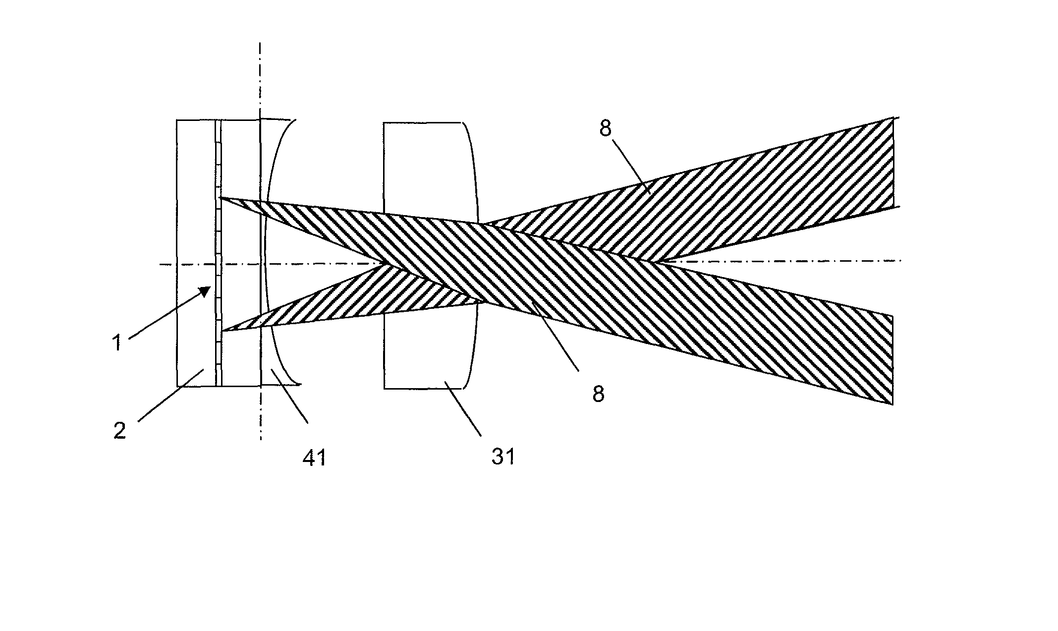
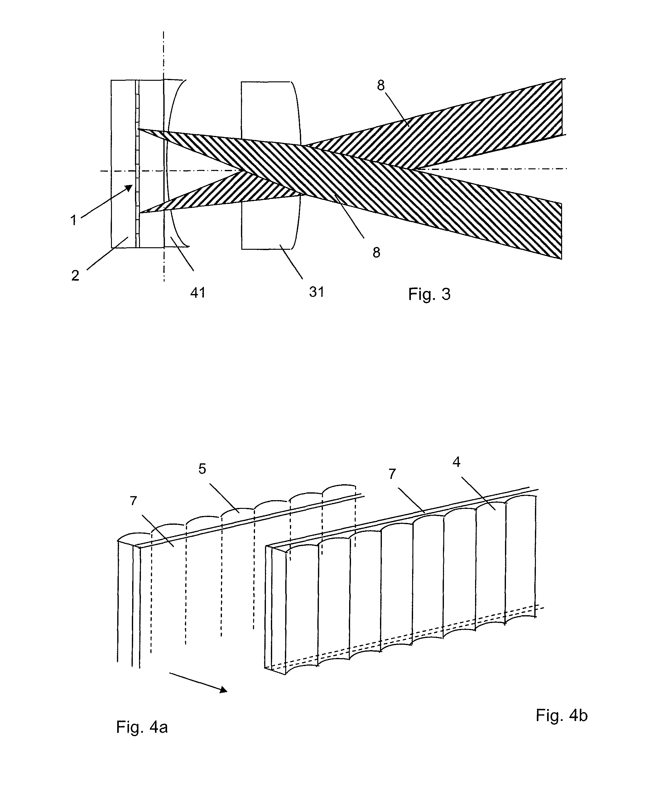
[0042]Now, the effect of the corrective matrix according to this invention during imaging of point elements with an imaging matrix will be described in greater detail.

[0043]The imaging matrix consists for example of imaging elements in the form of stripes or lenses. The illumination matrix consists of a multitude of illumination elements.

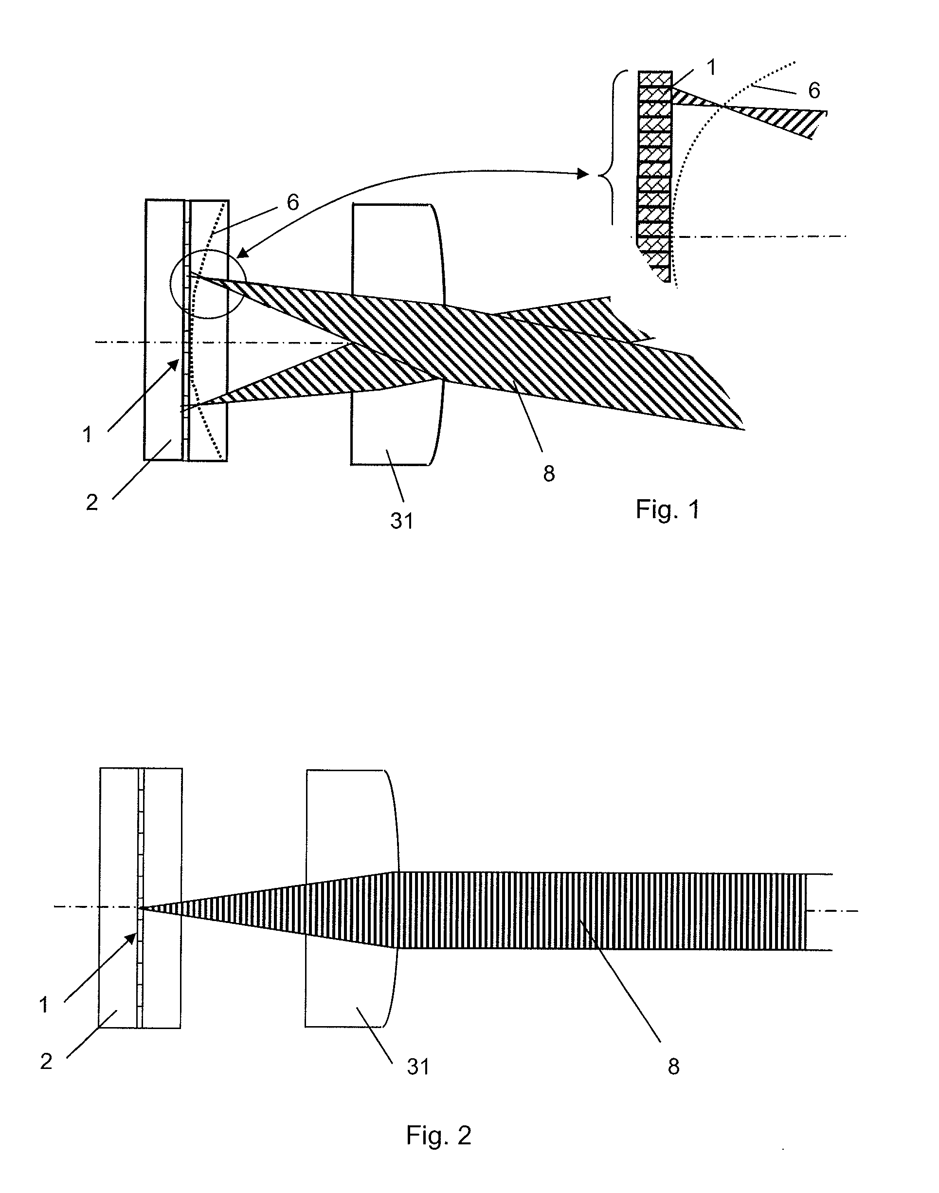
[0044]FIG. 1 illustrates, in simplified form, the effect the field curvature has in an autostereoscopic multi-user display. The field curvature represents the actual course of the rear focal points of inclined rays, which arises during the imaging of illumination elements through an imaging element of an imaging matrix. The illumination matrix (only partly shown in the figure), for example a shutter 2, contains a number of pixels 1 as illumination elements. An imaging matrix in the form of a lenticular with parallel, stripe shaped lenticules 31 as imaging elements for focusing light on to viewer's eyes, seen in the direction of light propagation, is...


PUM


Abstract

The invention relates to an image display device comprising an imaging matrix, which consists of imaging elements which are arranged in a lateral manner, for example, lenticulars or a lens array, and a plurality of point elements which are disposed on a object plane and which are formed from the imaging elements in an observation chamber. In order to reduce imaging errors resulting in the image field curvature of the individual imaging elements of a large observation angle, compensation by a correction matrix, which contains a plurality of optical corrections elements, takes place. An optical correction element is associated with each individual optical imaging element. Said invention can be used, for example, in image or video display devices, such as autostereoscopic displays, multi-user-displays with sweet-spot-units and multi-view-displays, in order to image illuminating elements. The invention also relates to displays comprising a sweet-spot-unit, which can be switched for one or more observers into a two-dimensional mode and also in an autostereoscopic mode.

Description

CROSS REFERENCE TO RELATED APPLICATIONS[0001]This application claims the priority of PCT / DE2006 / 000116 filed on Jan. 19, 2005 and DE 10 2005 004 303.8 filed on Jan. 24, 2005, the entire contents of which are hereby incorporated in total by reference.FIELD OF THE INVENTION[0002]The invention relates to an image display device comprising an imaging matrix which consists of laterally arranged imaging elements, such as lenticulars or lens arrays. More specifically, the imaging elements may be spherical or aspherical lens elements, holographic optical elements (HOE) or optical imaging elements of any other type which are combined with or among each other, arranged in the direction of light propagation in stacks.DESCRIPTION OF RELATED ART[0003]This invention may, for example, be applied to image illumination elements in image or video display devices such as autostereoscopic displays, multi-user displays with sweet spot unit and multi-view displays. Further, this invention can advantageou...

Claims


Application Information

Patent Timeline
IPC IPC(8): H04N13/02G02B30/27
CPCG02B27/2214G02B27/2228H04N13/0404H04N13/0418H04N13/0456H04N13/305H04N13/32H04N13/361G02B30/34G02B30/27G02B30/00
Inventor SCHWERDTNER, ARMIN
Owner SEEREAL TECHNOLOGIES
Why Eureka
Try Eureka