Mounting device for an injector in an exhaust system of an internal combustion engine

an injector and exhaust system technology, applied in the direction of machines/engines, transportation and packaging, pipe heating/cooling, etc., can solve the problems of excessive overheating of electromagnetic injectors, inability to recommend the storage of ammonia within the car, etc., to achieve effective heat loss, easy and cost-effective implementation

Active Publication Date: 2012-09-11
MARELLI EURO SPA
View PDF15 Cites 18 Cited by
  • Summary
  • Abstract
  • Description
  • Claims
  • Application Information

AI Technical Summary

Benefits of technology

[0008]It is the object of the present invention to provide a mounting device for an injector in an exhaust system of an internal combustion engine, such a mounting device being easy and cost-effective to implement, not displaying the above disclosed drawbacks and, in particular, ensuring an appropriate thermal insulation of the injector from the heat of the exhaust system allowing at the same time an effective heat loss by the injector itself.

Problems solved by technology

However, for obvious safety reasons connected to the toxicity of ammonia, is not recommendable to store ammonia within a car.
However, mounting in an exhaust conduit arranged immediately upstream an SCR catalytic converter of an electromagnetic injector originally made for the injection of fuel has revealed problematic, as the temperatures within the exhaust conduit are very high (from a minimum of about 150° C. to a maximum of about 900° C. during the regeneration steps) and may produce an excessive overheating of the electromagnetic injector with the subsequent destruction of the electromagnetic injector itself.

Method used


Image

  • Mounting device for an injector in an exhaust system of an internal combustion engine
  • Mounting device for an injector in an exhaust system of an internal combustion engine
  • Mounting device for an injector in an exhaust system of an internal combustion engine

Examples


Embodiment Construction

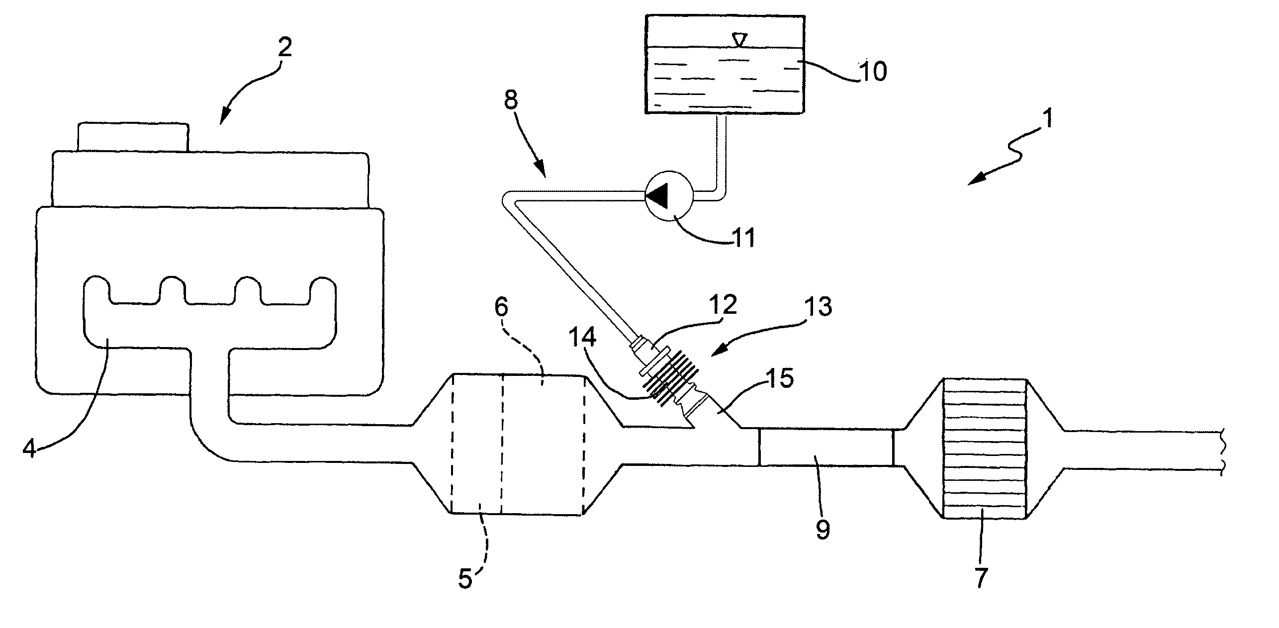
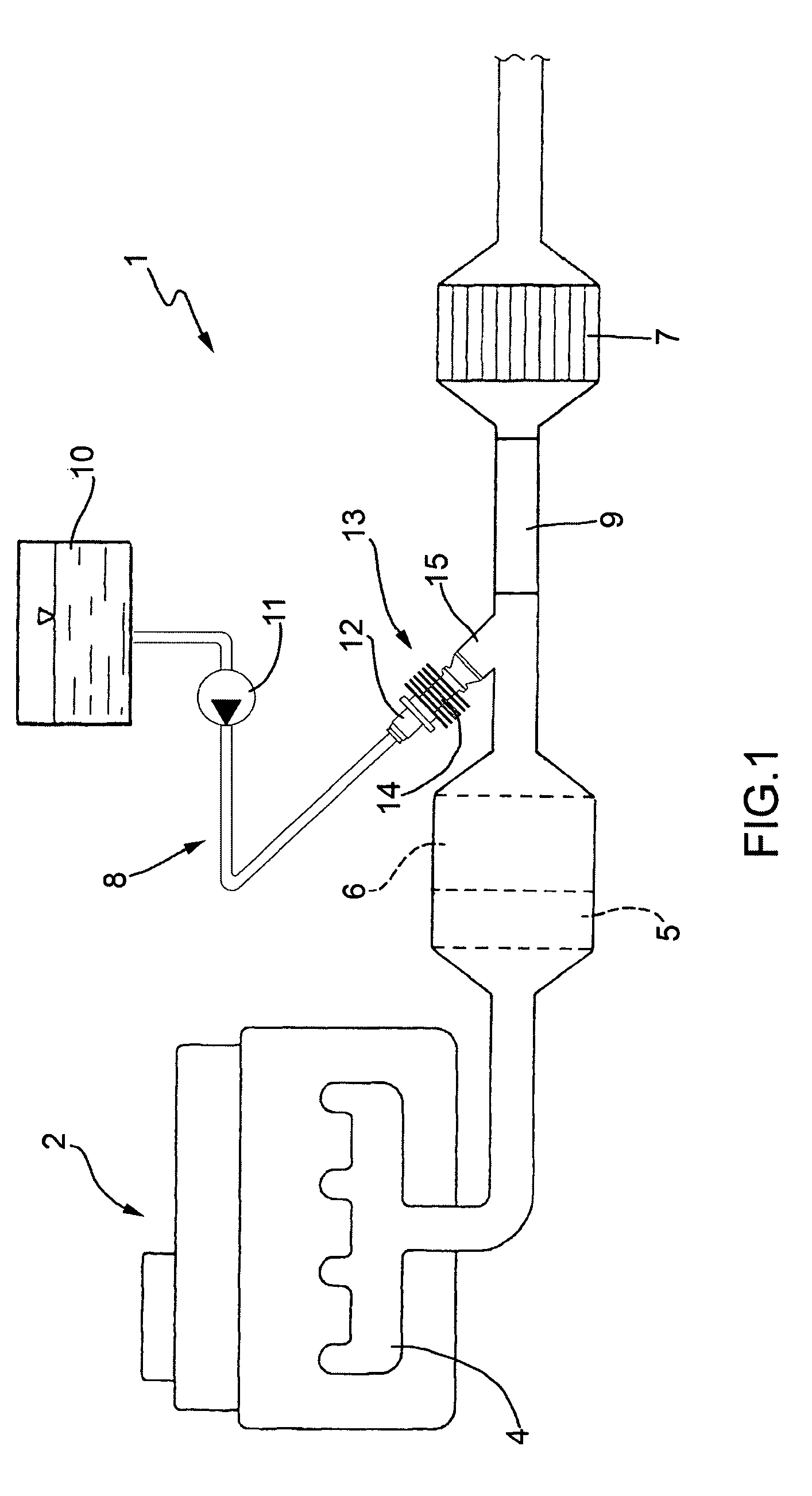
[0014]In FIG. 1, numeral 1 indicates as a whole an exhaust system for an internal combustion engine 2 operating according to the “Diesel” cycle (i.e. fed with diesel fuel or the like).

[0015]The exhaust system 1 emits the gases produced by the combustion to the atmosphere and comprises an exhaust conduit 3 which extends from an exhaust manifold 4 of the internal combustion engine 2. An oxidation catalyst 5 and a particle filter 6 are arranged along the exhaust conduit 3; in FIG. 1, the oxidation catalyst 5 and the particle filter 6 are arranged one after the other within the same common tubular container.

[0016]Furthermore, a Selective Catalytic Reduction (SCR) system for the post-treatment of NOx (NO and NO2) molecules is arranged along the exhaust conduit 3 and downstream of the oxidation catalyst 5. The SCR catalytic system 7 may comprise a single SCR catalytic converter as shown in FIG. 1, or it may comprise a set (normally three) catalytic converters which together optimize the S...


PUM


Abstract

A mounting device for an injector in an exhaust system of an internal combustion engine; the mounting device is provided with a tubular support body, which is made of a thermally conductive material, houses the injector therein, and is adapted to be coupled to a connection tube laterally extending outwards from an exhaust conduit of the exhaust system at a lower end thereof; an upper portion of the support body is thermally coupled to an upper portion of a nose of the injector so that a high thermal exchange occurs by conduction between the upper portion of the nose of the injector and the upper portion of the support body; and a lower portion of the support body is thermally insulated from a lower portion of the nose of the injector so that a reduced thermal exchange occurs by conduction between the upper portion of the nose of the injector and the upper portion of the support body.

Description

TECHNICAL FIELD[0001]The present invention relates to a mounting device for an injector in an exhaust system of an internal combustion engine provided with exhaust-gas post-treatment.[0002]The present invention is advantageously applied to an electromagnetic injector, to which explicit reference will be made in the following description without therefore loosing in generality.BACKGROUND ART[0003]The future international standards relating to the control of the emissions of polluting gases produced by cars (the so-called “Euro5” and “Euro6” or “Tier2 Bin5” standards) provide for a very low limit for the NOx molecules which may be released in the atmosphere.[0004]Respecting such limits is particularly important especially for diesel engines; for this reason, it has been suggested to provide the exhaust system of a diesel engine with an additional NOx Selective Catalytic Reduction (SCR) converter adapted to convert the molecules of NOx (NO2 or NO) to nitrogen (N2), which is an inert ga...

Claims


Application Information

Patent Timeline
Patent Type & Authority Patents(United States)
IPC IPC(8): F01N3/00
CPCF01N3/2066F01N2260/022F01N2610/02F01N2610/11F01N2610/1453Y02T10/24Y10T137/6525Y02T10/12
Inventor OSBAT, GIOVANNIGRIMALDI, CARLO NAZARENOCOMINETTI, PAOLOMARIANI, ALESSANDRO
Owner MARELLI EURO SPA
Why Eureka
Try Eureka