Wind apparatus

a technology of wind generator and wind power, which is applied in the direction of propellers, propulsive elements, water-acting propulsive elements, etc., can solve the problems of reducing the efficiency of the impeller itself and, consequently, the electrical generator connected thereto, and the cost of installation and maintenance of the generator, so as to achieve the effect of easy and cost-effective implementation

Inactive Publication Date: 2008-06-05
KNOW HOW ITALA
View PDF4 Cites 6 Cited by
  • Summary
  • Abstract
  • Description
  • Claims
  • Application Information

AI Technical Summary

Benefits of technology

[0011]It is therefore the main object of the present invention to make a wind apparatus which is free from the above-described drawbacks and which is, at the same time, easy and cost-effective to implement.

Problems solved by technology

It is known that supplying electricity to streetlamps, road signs, emergency telephones, etc. is very expensive because it requires an extensive distribution network constituted by buried electric cables, the installation of which is expensive both in terms of employed materials and due to the specialized manpower which is required.
However, despite working in a fairly satisfactory manner, the apparatuses described in the aforesaid documents do not fully exploit the power of the wind which strikes the impeller because, as explained in greater detail below, a portion of the wind energy is lost, thus considerably decreasing the efficiency of the impeller itself and, consequently, also of the electric generator connected thereto.

Method used


Image

  • Wind apparatus
  • Wind apparatus
  • Wind apparatus

Examples


first embodiment

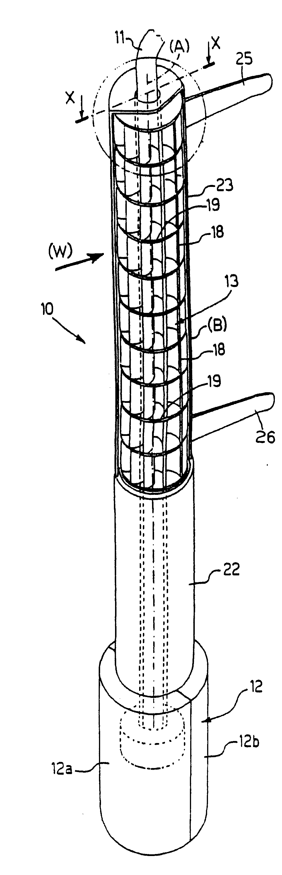
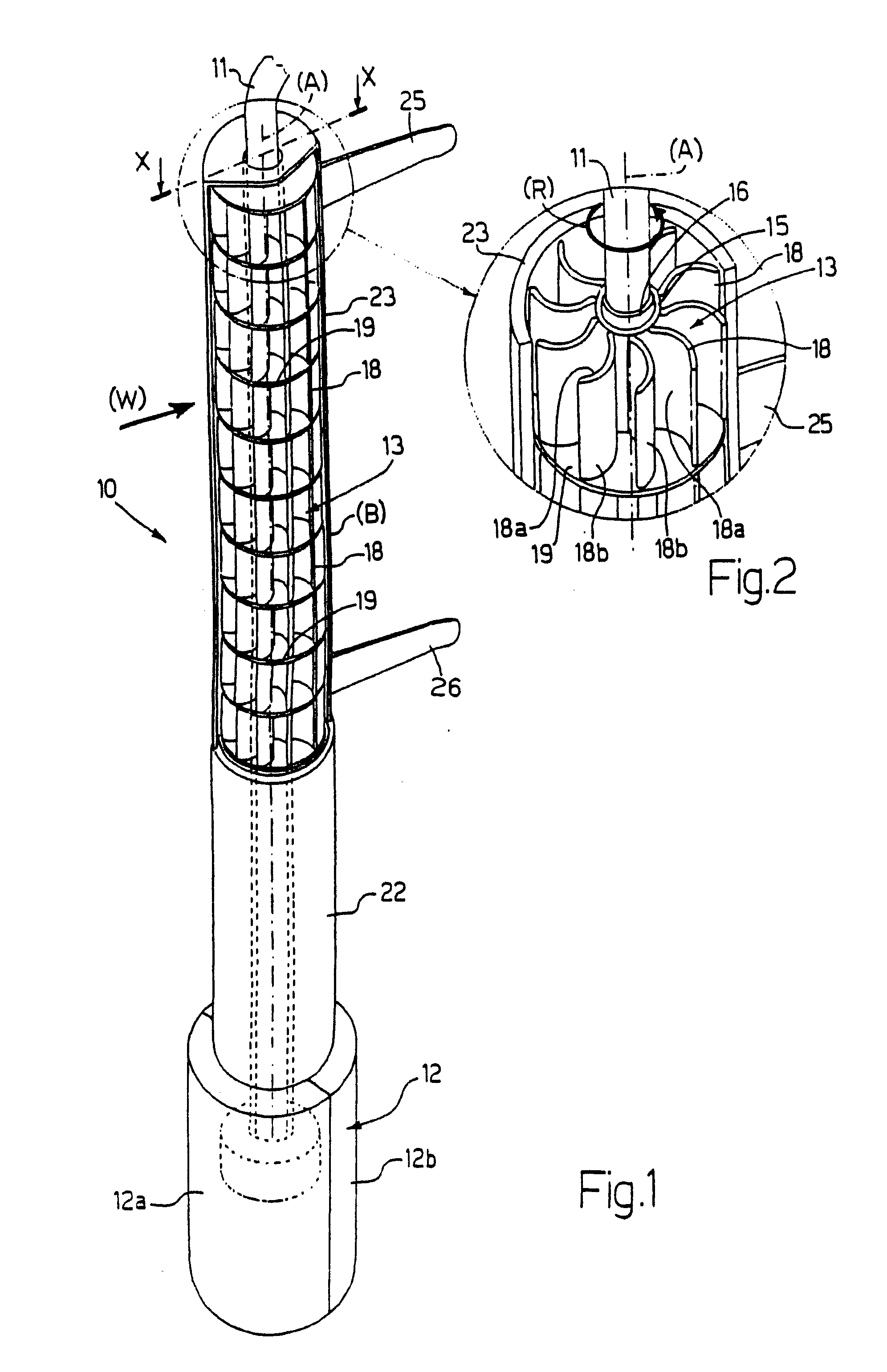
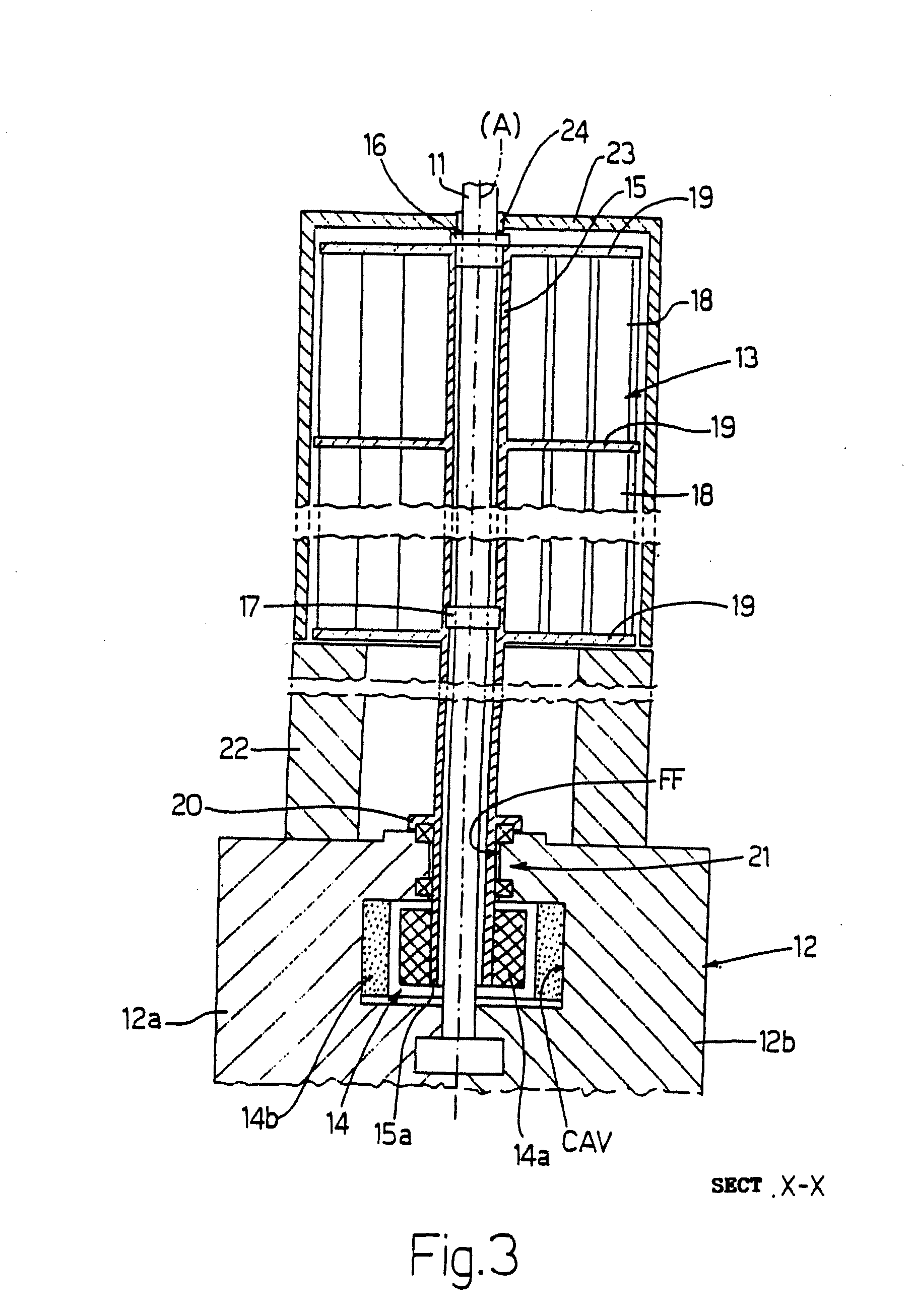
[0019]As shown in FIGS. 1-3, in a first embodiment thereof, the apparatus 10 comprises a rod 11 (with longitudinal and vertical symmetry axis (A)) fixed to a base 12. On the rod 11, on the side opposite to the base 12, there is provided a lamp (not shown in the accompanying figures) directly powered by the electric energy produced by a wind impeller 13 in concert with a wind generator 14 (see below).

[0020]The wind impeller 13, in turn, comprises a hub 15 coaxial with the axis (A) of the rod 11. Furthermore, the rod 11 is inside the hub 15 and a pair of bearings 16, 17 onto which the weight of the entire impeller 13 is relieved, are keyed thereon. The bearings 16, 17 allow the relative rotation of the impeller 13 itself with respect to the rod 11.

[0021]A plurality of essentially tile-shaped blades 18 is integral with the hub 15. Each tile presents a corresponding concave surface 18a and a corresponding convex surface 18b.

[0022]In embodiment shown in FIGS. 1-3, the wind impeller 13 i...

second embodiment

[0041]FIG. 4 shows the invention in which the traditional blades 18 of the impeller 13, which were previously illustrated with reference to FIGS. 1-3, are replaced by a plurality of propeller segments 180 of an impeller 13*.

[0042]For example, the propeller segment 180* shown in FIG. 4 contemplates a first surface 180*a and a second surface 180*b.

[0043]For the previously explained reasons, the second surface 180*b must be shielded by the wind screen hood 23* with which two rudders 25* and 26* are integral. As the wind direction given by the arrow (W) changes, the position of the wind screen hood 23* will also change with the implications which have been described with reference to the first embodiment shown referring to FIGS. 1-3.

[0044]Obviously, a generator (not shown) of the previously seen type is associated to the impeller 13*.

[0045]In a further embodiment (not shown), at least one portion of the wind screen hood is scroll-shaped to create an air inlet funnel, in which the air it...


PUM


Abstract

A wind apparatus which specifically comprises an essentially semi-cylindrical-shaped wind screen hood adapted to rotate about a vertical axis. The wind screen hood is external to a wind impeller and is put into rotation (to reach a position of balance) by rudders actuated by the wind so as to cover a portion of a plurality of radial thrust elements according to the direction of the wind itself.

Description

RELATED APPLICATION[0001]The present application claims priority of Italian Patent Application No. BO2006A 000786 filed Nov. 20, 2006, which is incorporated herein in its entirety by this reference.FIELD OF THE INVENTION[0002]The present invention relates to a wind generator. Specifically, the present invention finds advantageous, but not exclusive, application in the field of lighting streets, highways, etc., to which explicit reference will be made in the following description without loss in generality.BACKGROUND OF THE INVENTION[0003]It is known that supplying electricity to streetlamps, road signs, emergency telephones, etc. is very expensive because it requires an extensive distribution network constituted by buried electric cables, the installation of which is expensive both in terms of employed materials and due to the specialized manpower which is required.[0004]In order to avoid the drawbacks due to the use of a centralized electric network for supplying electricity to str...

Claims


Application Information

Patent Timeline
Patent Type & Authority Applications(United States)
IPC IPC(8): F03D3/04
CPCF03D3/005F03D3/0418F03D3/0472F03D9/002Y02E10/74F05B2240/911F05B2240/913Y02E10/728F05B2240/216F03D9/25F03D3/02
Inventor BERNARDI, WLADIMIRO
Owner KNOW HOW ITALA
Why Eureka
Try Eureka