Valve for adjusting the air flow rate in an internal combustion engine

a valve and air flow technology, applied in the direction of valves, mechanical equipment, machines/engines, etc., can solve the problems of increasing the use of materials, increasing the cost of operation, and affecting the operation of the valve, so as to achieve the effect of easy and cost-effective operation

Active Publication Date: 2010-10-19
FAB ITAL MAGNETI MARELLI SPA
View PDF8 Cites 6 Cited by
  • Summary
  • Abstract
  • Description
  • Claims
  • Application Information

AI Technical Summary

Benefits of technology

[0009]It is the object of the present invention to provide a valve for adjusting the air flow rate in an internal combustion engine, which valve is free from the above-described drawbacks and, specifically, is easy and cost-effective to implement.

Problems solved by technology

However, it has been observed that at the connection point with the reinforcement columns, the cylindrical tubular pipe tends to presents deformations related to the phenomenon of “shrinkage” of the plastic material during the step of moulding.
Such deformations of the cylindrical tubular pipe are particularly detrimental, because they alter the geometry of the air introduction channel in an area very close to (or even coinciding with) the valve seat concerned by the butterfly valve plate and thus determine an alteration of the butterfly valve performances.
In order to eliminate the presence of the reinforcements columns, it has been suggested to make a very thick connection flange (at least 15 mm); however, such constructive solution implies both a use of more material (and thus a higher cost and a heavier weight), and greater complications in the step of moulding of the valve body.

Method used


Image

  • Valve for adjusting the air flow rate in an internal combustion engine
  • Valve for adjusting the air flow rate in an internal combustion engine
  • Valve for adjusting the air flow rate in an internal combustion engine

Examples


Embodiment Construction

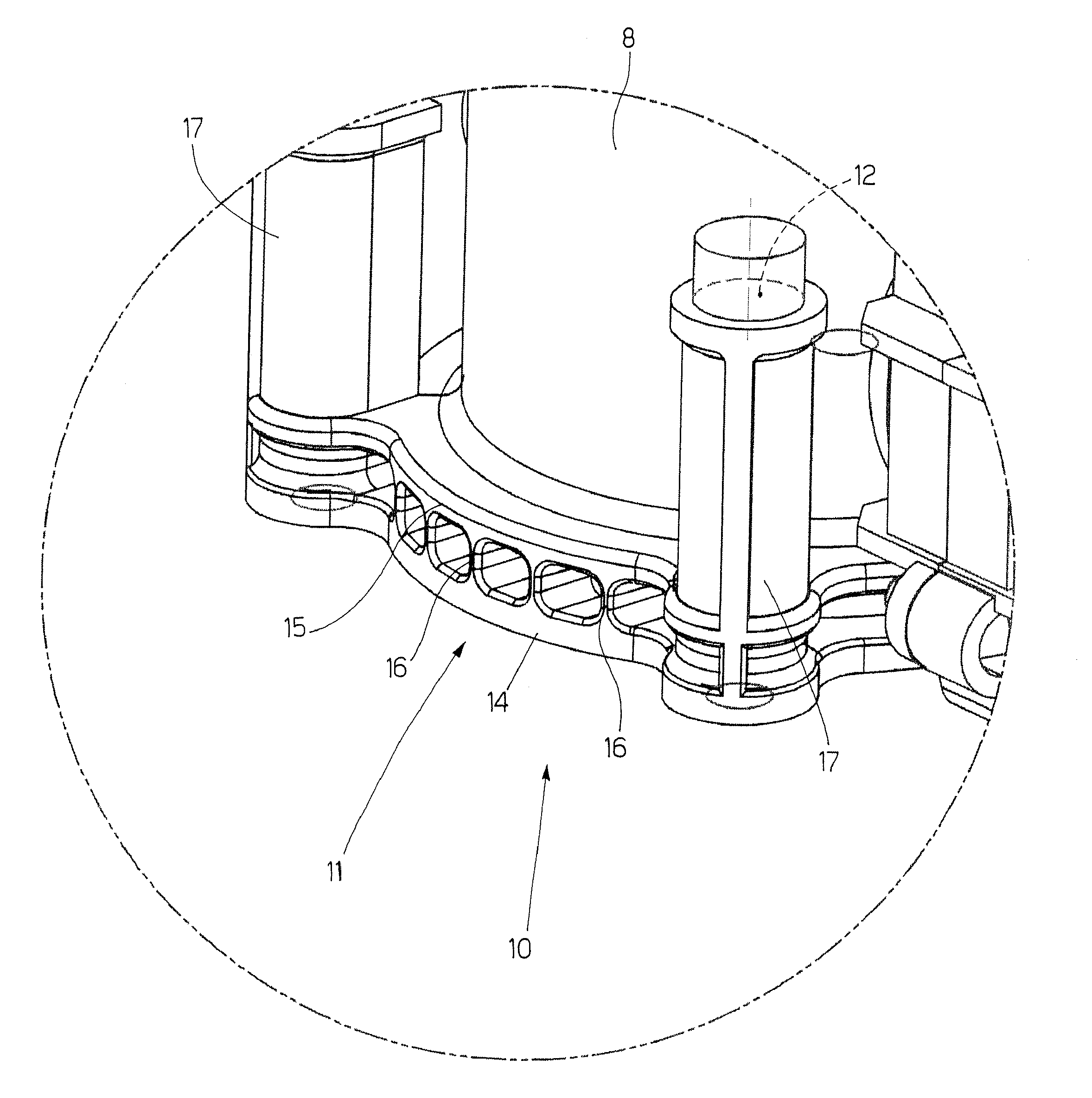
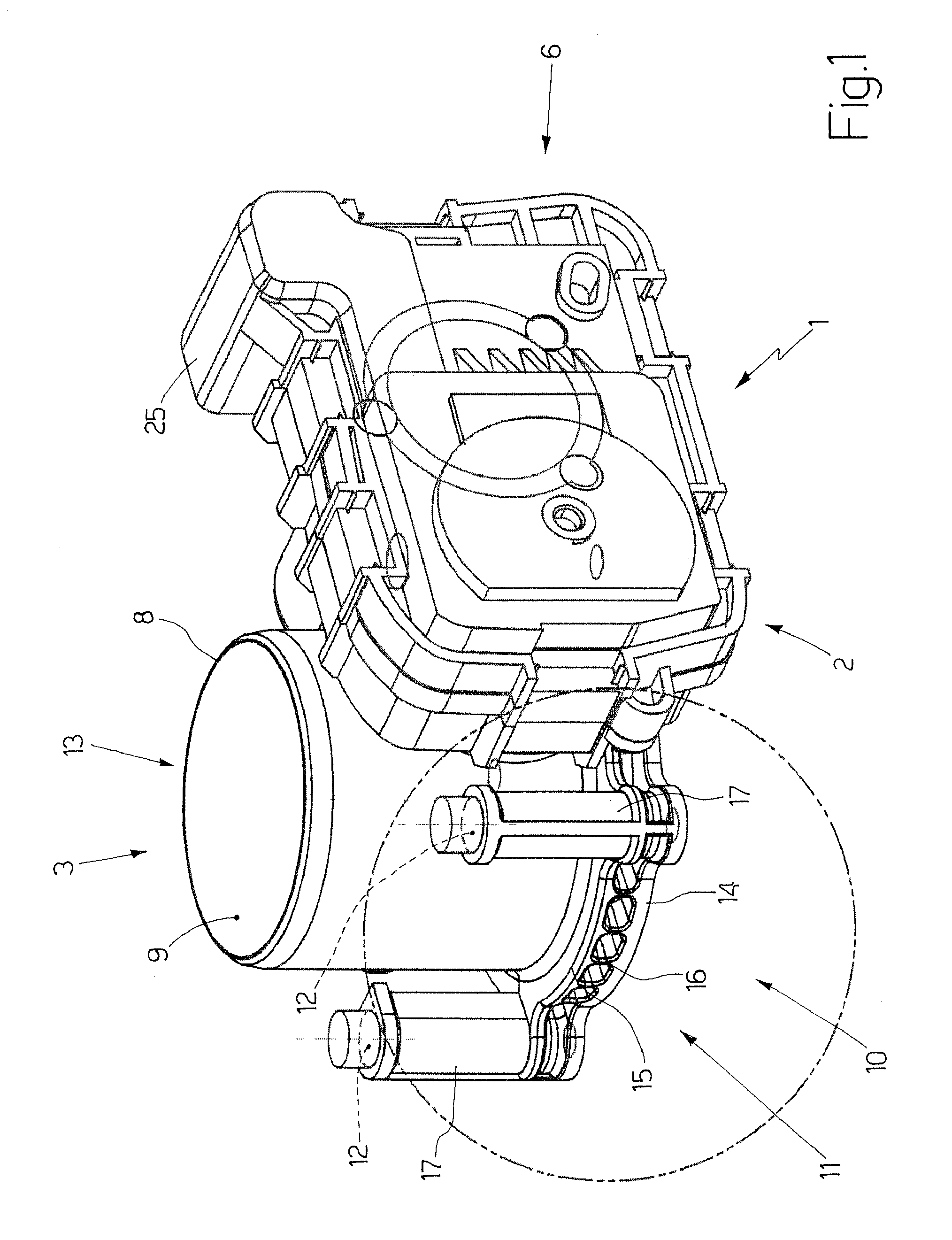
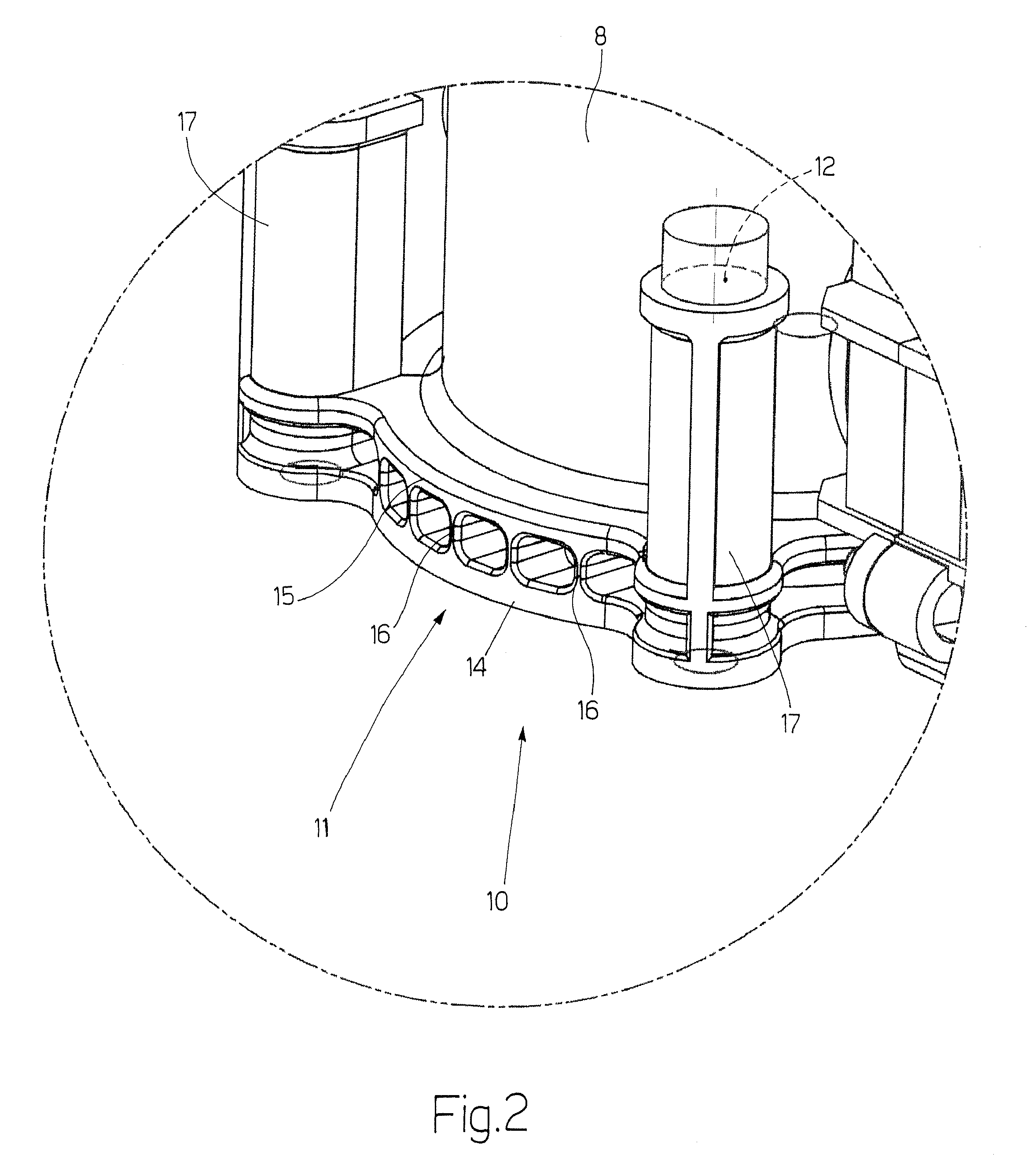
[0019]In FIG. 1, numeral 1 indicates as a whole an electronically controlled butterfly valve for an internal combustion engine (not shown). Butterfly valve 1 comprises a valve body 2 formed by moulded plastic material (e.g. PPS—polyphenylene sulphide) and consisting of a valve module 3, in which there is obtained a valve seat engaged by a butterfly valve plate 4 (shown in FIG. 3) which is provided with a rotational shaft 5 (shown in FIG. 3) to rotate between an opening position and a closing position of the valve seat itself, and an actuation module 6, in which there is accommodated an actuation system 7 (shown in FIG. 7) to displace butterfly valve plate 4 from the opening position to the closing position of the valve seat.

[0020]Valve module 3 comprises a cylindrical tubular pipe 8, within which there is defined an air introduction channel 9 along which the valve seat is defined and butterfly valve plate 4 is thus arranged. At a first end 10 of cylindrical tubular pipe 8, there is ...


PUM


Abstract

A valve for adjusting the air flow rate in an internal combustion engine; the valve presents: a valve body; a cylindrical tubular pipe obtained within the valve body and in which an air introduction channel is defined; a valve seat obtained along the air introduction channel of the tubular pipe; an actuation system; a shutter, mobile under the bias of the actuation system; and a connection flange, which is integral with a first end of the tubular pipe and presents a plurality of through holes which are crossed in use by corresponding fastening screws for rigidly fixing the valve body; the connection flange is provided with a lower plate and an upper plate, which are reciprocally parallel, facing and distanced and are arranged radially with respect to the cylindrical tubular pipe, and a number of ribs, which reciprocally connect the plates, are arranged perpendicularly to the plates, and are arranged axially with respect to the cylindrical tubular pipe.

Description

TECHNICAL FIELD[0001]The present invention relates to a valve for adjusting the air flow rate in an internal combustion engine.[0002]The present invention is advantageously applied to a butterfly valve for adjusting the air flow rate upstream of an intake manifold of an internal combustion engine.BACKGROUND ART[0003]In petrol-fed internal combustion engines, there is contemplated a butterfly valve which is arranged upstream of an intake manifold and adjusts the flow rate of the air which is fed to the cylinders. A known butterfly valve presents a valve body accommodating a valve seat engaged by a butterfly valve plate, which is keyed onto a rotational shaft to turn between an opening position and a closing position by effect of the action of an electrical motor coupled to the shaft itself by means of a geared drive.[0004]A position sensor, which is adapted to detect the angular position of the shaft (i.e. of the butterfly valve plate), is coupled to one end of the shaft to allow a c...

Claims


Application Information

Patent Timeline
Patent Type & Authority Patents(United States)
IPC IPC(8): F16K51/00
CPCF02D9/1035F02D9/107F02D9/108
Inventor COLLI, MARCELLOBELLATO, NAZARIOMUSOLESI, STEFANO
Owner FAB ITAL MAGNETI MARELLI SPA
Why Eureka
Try Eureka