Micro-Fluidic System

a microfluidic system and microfluidic technology, applied in the direction of branching pipes, pipes/joints/fittings, pipes, etc., can solve the problems of high energy consumption and considerable wear, pneumatic actuators having the suitable size to create both depressions and compressions, and the preparation of this type of valves is often complex and expensive, so as to achieve easy and cost-effective effect of implementation

Active Publication Date: 2013-02-14
MENARINI SILICON BIOSYSTEMS SPA
View PDF18 Cites 5 Cited by
  • Summary
  • Abstract
  • Description
  • Claims
  • Application Information

AI Technical Summary

Benefits of technology

[0008]It is an object of the present invention to provide a micro-fluidic system, which allows to overcome, at least partially, the drawbacks of the state of the art and are, at the same time, easy and cost-effective to implement.

Problems solved by technology

A first series of drawbacks derives from the fact that the pneumatic actuator needs to always be active (both when the valve is to be opened, and when the valve is to be closed).
This determines a high energy consumption and a considerable wear.
It should also be noted that pneumatic actuators having the suitable size to create both a depression and a compression are relatively complex and expensive.
Furthermore, it should be noted that the preparation of this type of valves is often complex.
Some of the problems in this connection are due to the fact that the membrane must often be selectively connected to the wall of the channel and not to the partition.
Further drawbacks of the state of the art are related to the fact that it is not always possible to correctly maintain the membrane in position and / or obtain an effective coupling between the membrane and the partition.

Method used


Image

  • Micro-Fluidic System
  • Micro-Fluidic System
  • Micro-Fluidic System

Examples


example 1

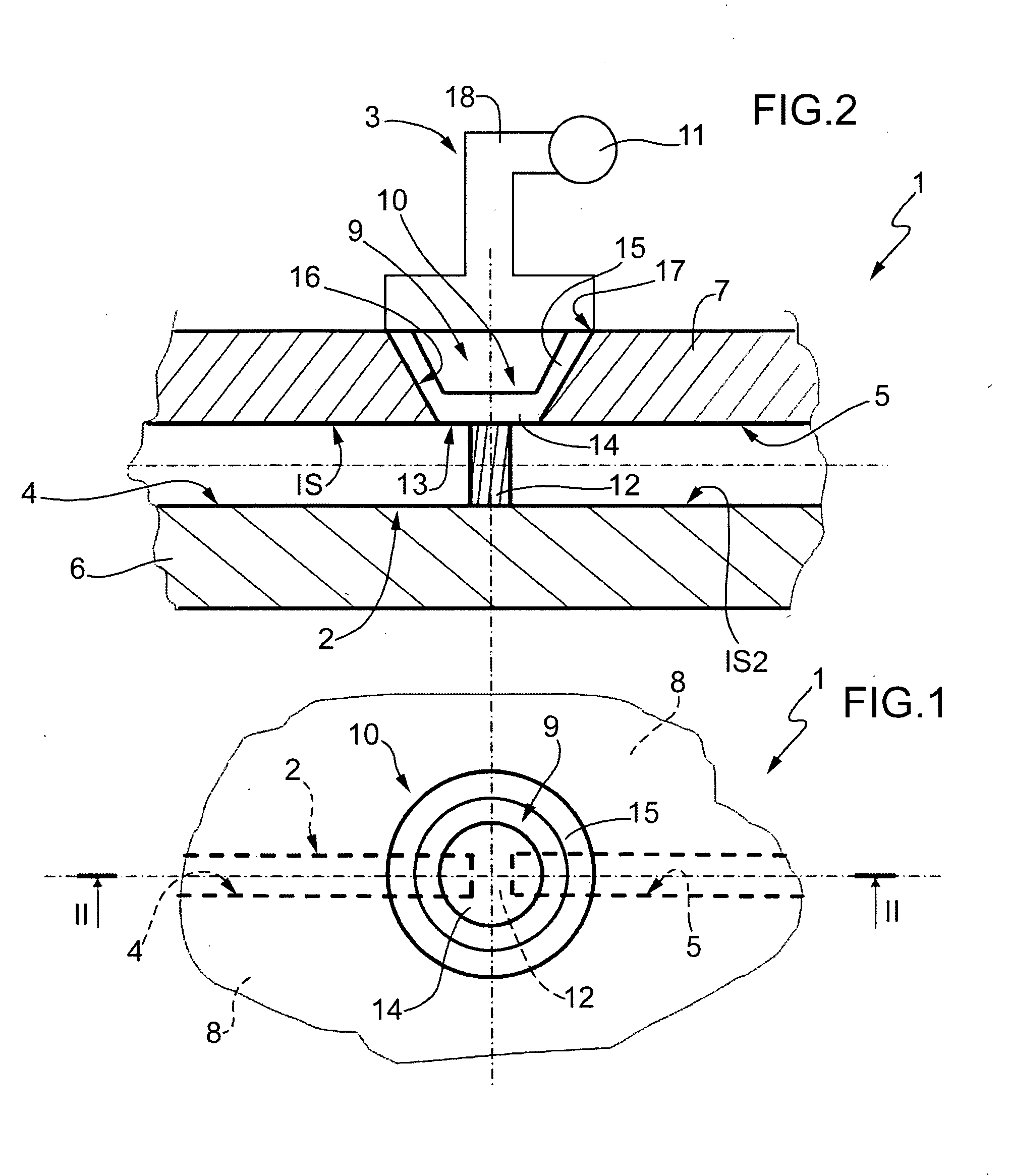
[0094]This example discloses the production of closing element 10 of the embodiment of FIGS. 1-4.

[0095]Closing element 10 was made of PDMS (polydimethylsiloxane) (Sylgard 184® of Dow Corning—it should be noted however that other materials may be used).

[0096]The hardening agent of PDMS (polydimethylsiloxane) and the base are mixed in a ratio of 1:10 and the mixture obtained thereby was poured in a hole 9 (FIG. 18) of a covering wall 7, which hole 9 is closed on the bottom by a base mould 23. PDMS was degassed in a vacuum chamber for one hour. A lid 24 is arranged on hole 9 to remove PDMS in excess and configure closing element 10 (FIG. 19). Wall 7 is inserted in an oven for 2 hours at 80° C. Closing element 10 is therefore obtained already connected to wall 7.

example 2

[0097]This example discloses an alternative embodiment of closing element 10 of the embodiment of FIGS. 1-4.

[0098]Closing element 10 was made of PDMS (polydimethylsiloxane) (Sylgard 184® of Dow Corning—it should be noted however that other materials may be used).

[0099]The hardening agent of PDMS (tetra methyl tetravinyl cyclotetrasiloxane) and the base were mixed in a ratio of 1:10 and the mixture obtained thereby was poured in a mould which reproduces the shape of closing element 10 in negative. PDMS was degassed in a vacuum chamber for one hour. A lid was arranged on mould 26 to remove PDMS in excess. The covered mould was inserted in an oven for 2 hours at 80° C. Closing element 10 was then extracted from the mould by using a cutter.

[0100]Closing element 10 and wall 7 are treated in a plasma reactor (Gambetti Plasma, Modello Tucano) by using the parameters of table 1 in O2 / N2 mixture.

TABLE 1Plasma activationPower, W40Voltage, V360Pressure, mbar0.3-0.4Time, s35

[0101]Closing elemen...

example 3

[0102]This example discloses the production of closing element 10 of the embodiment of FIG. 5.

[0103]Closing element 10 of FIG. 5 is obtained following the procedure disclosed in example 1 and using a base mould 23, a lid 24 and a wall 7 therefor as shown in FIGS. 6 and 7.


PUM


Abstract

A micro-fluidic system comprising a micro-fluidic channel, which has a wall provided with a hole; a closing element, which is partially housed within the hole and has a membrane portion adapted to deform and a side portion sealingly connected with the above mentioned wall; and a partition arranged within the micro-fluidic channel between a first and a second segment; the closing element is deformable between a locked configuration in contact with the partition and an open configuration spaced from the partition; the closing element may be deformed by suction or by a rod or a piston.

Description

TECHNICAL FIELD[0001]The present invention relates to a microfluidic system.BACKGROUND ART[0002]In the micro-fluidic field there is known a type of system comprising a channel, which includes two segments connected to one another by a valve. The valve usually includes a partition arranged along the channel to separate the two segments and a membrane of an elastomeric material connected to a wall of the channel in the area of two holes, each of which is arranged at an end of a respective segment in the area of the partition. The valve further comprises a pneumatic actuator, which is adapted: on one side, to create a depression so as to deform the membrane and, therefore, connect the two segments of the channel; on the other side, to exert a pressure to push the membrane against the wall of the channel so as to close the two holes and isolate the two segments.[0003]Known valves and circuits of the above indicated type are for example disclosed in WO2008115626 (see in particular FIG. 2...

Claims


Application Information

Patent Timeline
Patent Type & Authority Applications(United States)
IPC IPC(8): F16L41/00
CPCF16K99/0001F16K99/0015F16K2099/0078F16K99/0059F16K2099/0074F16K99/0034Y10T137/85938
Inventor MANARESI, NICOLMEDORO, GIANNICALANCA, ALEX
Owner MENARINI SILICON BIOSYSTEMS SPA
Why Eureka
Try Eureka