Rotary valve

Active Publication Date: 2012-09-11
KYB CORP
View PDF7 Cites 60 Cited by
  • Summary
  • Abstract
  • Description
  • Claims
  • Application Information

AI Technical Summary

Problems solved by technology

However, in the conventional rotary valve, it was only possible to set the flow channel area to either one of maximum or minimum when changing the flow channel area by rotating the tubular valve body in relation to the housing.

Method used


Image

  • Rotary valve
  • Rotary valve
  • Rotary valve

Examples


Embodiment Construction

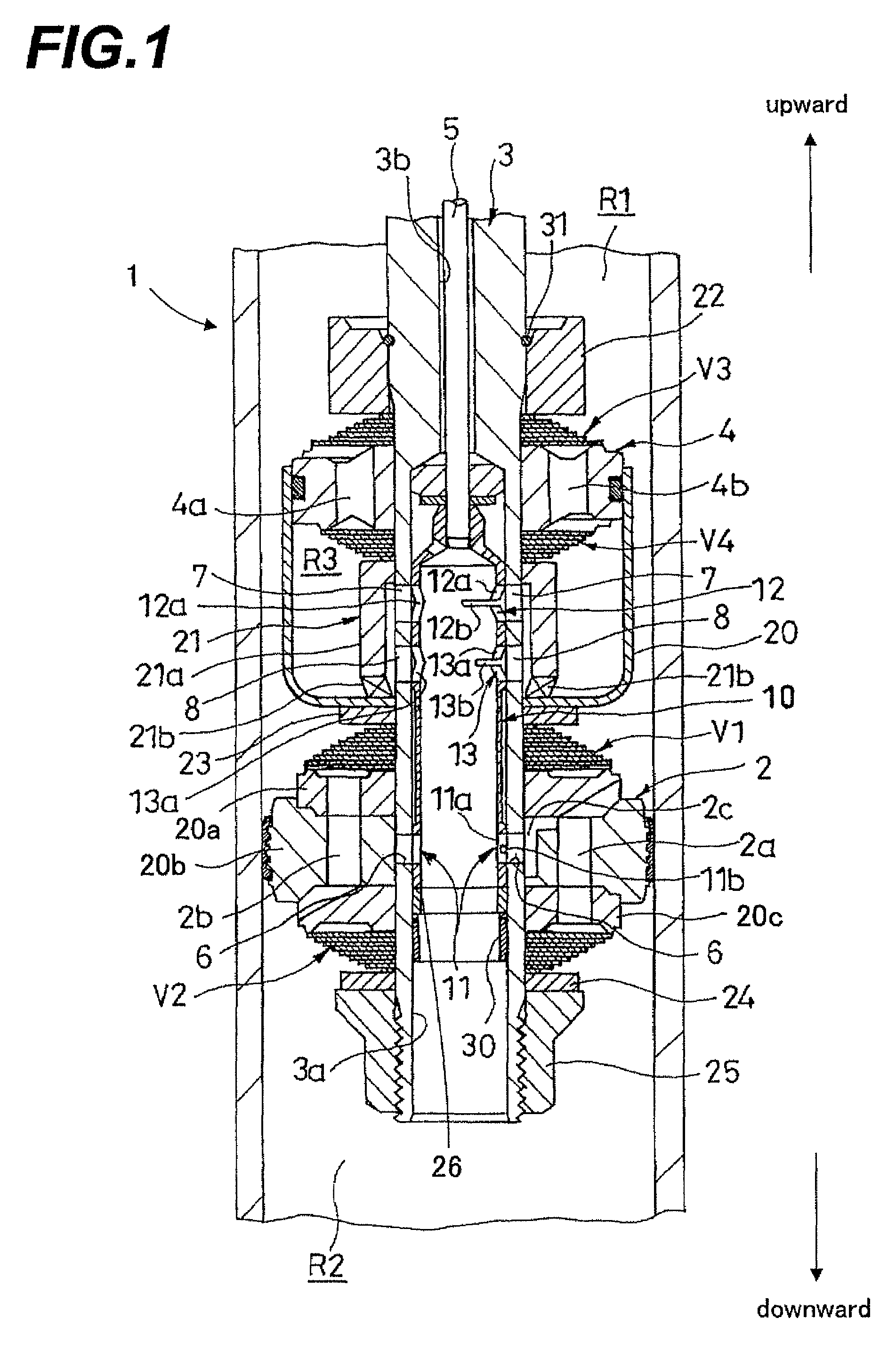
[0017]The rotary valve of the present invention is, for example, used by being applied to a damper for damping force adjustment. This damper is, for example, used in a vehicle. FIG. 1 is a longitudinal sectional diagram of a part of the damper equipped with the rotary valve in the embodiment of the present invention.

[0018]The damper illustrated in FIG. 1 comprises a cylinder 1, a piston 2 and a piston rod 3. The piston 2 is inserted in the cylinder 1 in a freely slidable manner and partitions inside of the cylinder 1 into the one chamber R1 and the other chamber R2. In FIG. 1, the one chamber R1 is located above the piston 2, and the other chamber R2 is located below. The piston rod 3 is inserted in the cylinder 1 in a freely movable manner through the piston 2.

[0019]In the cylinder 1, the working fluid such as hydraulic oil is charged. The upper end and the lower end of the cylinder 1 is closed by a closing member (not illustrated) to maintain inside of the cylinder 1 under the liq...


PUM


Abstract

In a rotary valve comprising a tubular housing (3) having, at the side part, a port (6) for communicating the inside and the outside thereof, and a tubular valve body (10) which is contained within the housing rotatably and has, at the side part, an orifice hole (11) capable of opposing to the port (6), the rotary valve of which the flow channel area formed by communicating the port (6) and the orifice hole (11) is changed by rotating the tubular valve body, at least one rotation stopping position with which the angle between the rotation stopping position at which the flow channel area is minimized and the rotation stopping position at which the flow channel area is maximized is equally divided, and the pressure loss differences between the adjacent rotation stopping positions are the same on condition that the passing flowing rate remains constant is provided.

Description

TECHNICAL FIELD OF THE INVENTION[0001]This invention relates to a rotary valve.BACKGROUND ART OF THE INVENTION[0002]A rotary valve provided with a tubular housing contained in a piston rod of a damper, and a tubular valve body rotatably inserted in this housing is known (See Japanese Utility Model Publication No. 62-117342). In this rotary valve, a port is formed by an oval hole extending along the circumferential direction and with variable widths in the axial direction at the side part of the housing, and the tubular valve body is provided with a circular hole capable of opposing to a part of the port.[0003]In the conventional rotary valve, the tubular valve body is rotated in relation to the housing, thereby changing the flow channel area of the hydraulic oil by changing the degree of overlapping between the port and the circular hole. In another word, the damping force generated by the damper is adjusted by changing the pressure loss caused when the hydraulic oil is passing thro...

Claims


Application Information

Patent Timeline
Patent Type & Authority Patents(United States)
IPC IPC(8): F16K5/10
CPCF16K5/0428
Inventor KAMO, SHUJIFUKUI, TAKAHIRO
Owner KYB CORP
Why Eureka
Try Eureka