Needle and tine deployment mechanism

a deployment mechanism and needle technology, applied in the field of medical devices and methods, can solve the problems of increasing the stress imparted to the needle, the ability to increase the exit angle, for example, by lengthening the ramp, and the ramp deflecting ramp, etc., to achieve the effect of improving and stabilizing the geometry, reducing the stress on the needle, and gradual bending radius

Active Publication Date: 2012-09-11
GYNESONICS
View PDF196 Cites 47 Cited by
  • Summary
  • Abstract
  • Description
  • Claims
  • Application Information

AI Technical Summary

Benefits of technology

[0014]The individual needles may be elastic or malleable, where suitable malleable needles are formed from stainless steel, titanium, or tungsten, gold, silver, or other conventional malleable metals. Suitable elastic needles may be formed from spring stainless steels, shape memory alloys, such as nitinol, eligiloy, and the like. In preferred aspects, the needles will be elastic with a pre-shaped straight configuration so that the portion of the needle passing over the ramp will be reversibly deflected with the portion of the needle distal to the ramp returning back to a straight configuration. It is desirable to minimize residual strain after multiple deflection or bending cycles. Residual strain can be minimized by ensuring the electrode material is not appreciably stressed beyond its elastic limit. This allows for repeatable needle electrode placements, and, thus, repeatable treatment ablation volumes.
[0031]The various embodiments described above significantly increase the number of times that the needle electrode deployment device may be used in a single procedure on a patient. Repeated deployment of the central electrode can often cause undue stress and wear, often resulting from interference and interaction with the exit port from the central electrode lumen or passageway, both as the central electrode is deployed and refracted as well as when the device is angled and manipulated in tissue during use. The particular needle exit configurations described above can lessen the stress and increase the deployable electrode life. In the case of the fixed center electrode, the requirement of repeated center electrode deployment is eliminated altogether.

Problems solved by technology

While such angles of deflection could theoretically be obtained by providing relatively short, sharply angled ramps, such short, steeply deflected ramps will increase the stress imparted to the needles.
The ability to increase the exit angle, for example, by lengthening the ramp, however, can be limited in certain designs, particularly designs having a relatively small diameter central member.

Method used


Image

  • Needle and tine deployment mechanism
  • Needle and tine deployment mechanism
  • Needle and tine deployment mechanism

Examples


Embodiment Construction

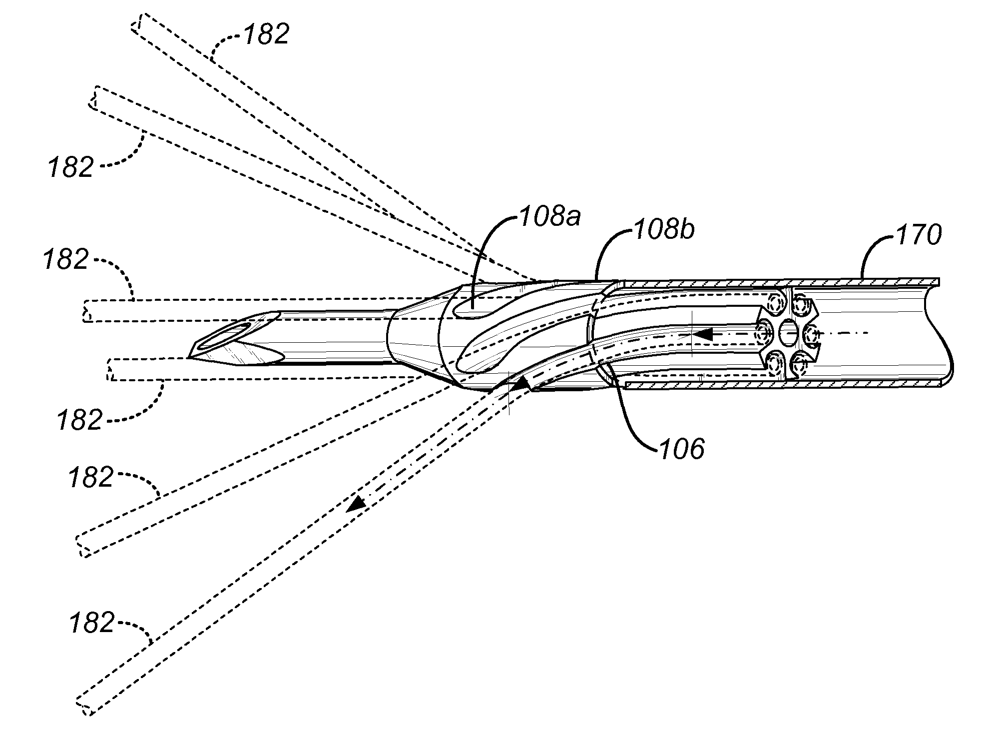
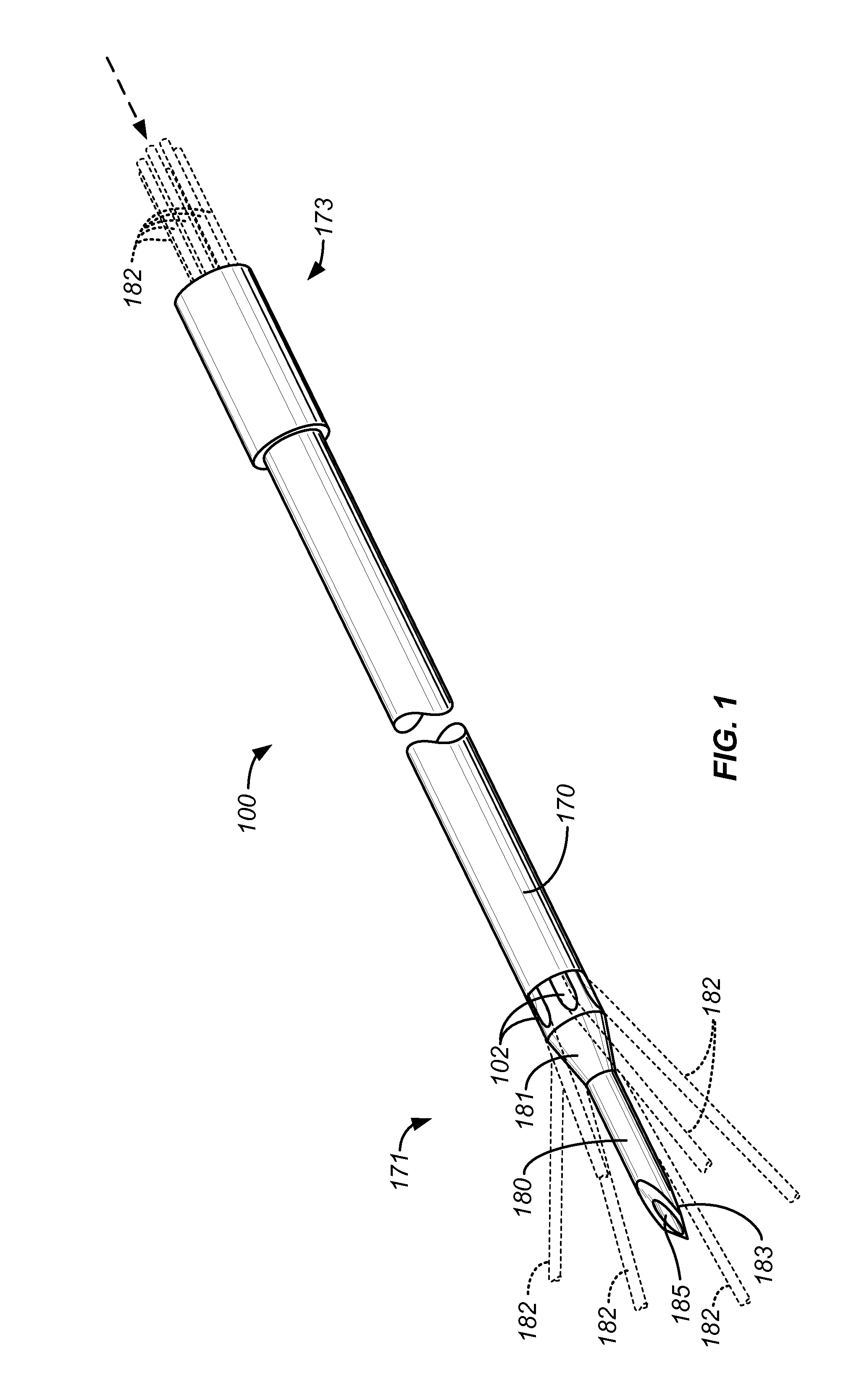
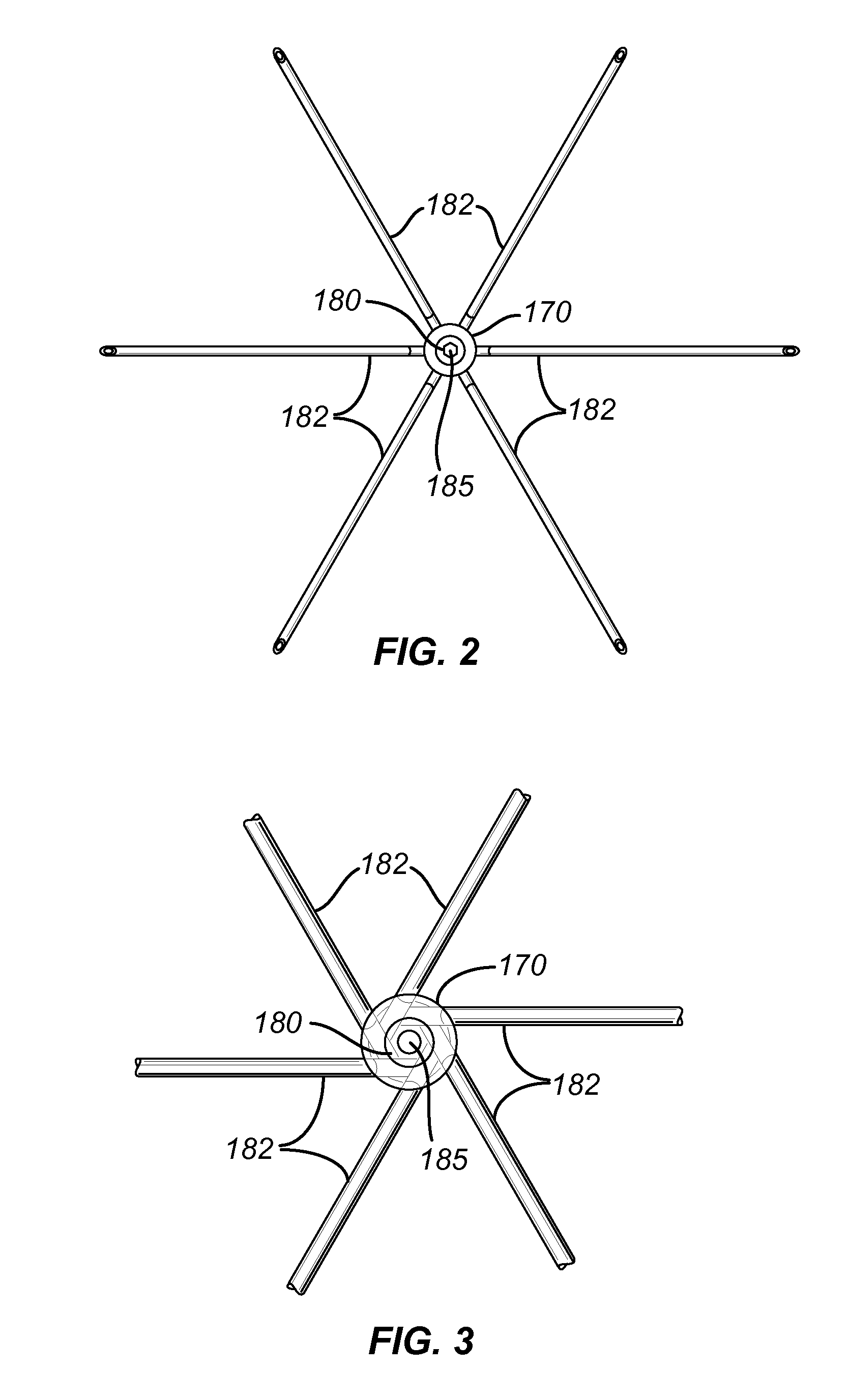
[0050]The present invention provides electrode deployment structures comprising needle electrode deployment shafts capable of reciprocatably deploying a plurality of needle electrodes into solid tissue. The needle electrode deployment shafts will comprise a central member having a proximal end, a distal end, and a longitudinal axis therebetween. Typically, the central member will have a distal end which is configured to permit self-penetration, e.g. the central member may itself be a needle having a sharpened or chamfered tip which permits the central member to be advanced into tissue by simply pushing. In other embodiments, the central member could comprise a hollow tubular body, commonly referred to as a cannula, having a needle or stylet removably received within a central lumen thereof. The cannula could then be introduced by placing the stylet with its sharpened tip extending from the distal end of the cannula and pushing the assembly of the cannula and stylet into tissue. The ...


PUM


Abstract

A needle electrode deployment shaft includes a central member and a plurality of needle electrodes. The central member has a plurality of needle advancement channels formed therein. The needle electrodes are disposed within the advancement channels and each advancement channel terminates in a ramp portion which deflects the needles radially outwardly as they are axially advanced. The ramps may be spirally or acutely configured in order to increase the distance through which the needles may be bent as they are axially advanced. Additionally, the central member may have a radially reduced distal tip in order to decrease tissue insertion forces.

Description

CROSS-REFERENCES TO RELATED APPLICATIONS[0001]The present application claims the benefit of provisional application 61 / 156,270, filed on Feb. 27, 2009, and is related to but does not claim the benefit of provisional patent application No. 61 / 091,708, filed on Aug. 25, 2008, the full disclosures of which are incorporated herein by reference.BACKGROUND OF THE INVENTION[0002]1. Field of the Invention[0003]The present invention relates generally to medical devices and methods. More particularly, the present invention relates to a therapy device having a deployable treatment needle with a plurality of tines deployable in a straight path from said needle.[0004]Uterine fibroids are benign tumors in the uterine wall and are the most common tumor of the female pelvis. Fibroids afflict up to 30% of women of childbearing age and can cause significant symptoms including discomfort, pelvic pain, mennorhagia (excessive bleeding), anemia, infertility, and miscarriage. While fibroids may be located...

Claims


Application Information

Patent Timeline
Patent Type & Authority Patents(United States)
IPC IPC(8): A61B1/313
CPCA61B18/1477A61B2018/00547A61B2018/00559A61B2018/00577A61B2019/528A61B2018/143A61B2018/1475A61B2019/5263A61B2018/1427A61B2034/2063A61B2090/3784
Inventor PLACEK, BRIANDECKMAN, ROBERT K.
Owner GYNESONICS
Why Eureka
Try Eureka