Ligation tool for endoscope and endoscopic ligation system

a technology which is applied in the field of ligation tool and endoscope ligation system, can solve the problems that the operation of setting the ligation tool of endoscope in the endoscope is fundamentally unnecessary, and achieve the effect of sufficient field of vision

Active Publication Date: 2012-09-11
OLYMPUS CORP
View PDF26 Cites 5 Cited by
  • Summary
  • Abstract
  • Description
  • Claims
  • Application Information

AI Technical Summary

Benefits of technology

[0010]Furthermore, it is unnecessary to attach a member, such as a cap, to the tip of the insertion portion of the endoscope. In addition, the insertion portion of the endoscope can be advanced and retreated relative to the tubular body, and can be made to project forward from the tip of the tubular body. Therefore, the field of vision of the endoscope is not obstructed, and a sufficient field of vision can be secured.
[0023]According to this ligation tool for endoscope, the negative pressure space for suction of a varix formed closer to the distal side than the seal portion can be set more narrowly. For this reason, a suction source with smaller capacity is satisfactorily used as a suction source of an air suction mechanism, and the time required for suction can also be further shortened.

Problems solved by technology

Thus, the operation for setting the ligation tool for endoscope in the endoscope is fundamentally unnecessary.
Furthermore, it is unnecessary to attach a member, such as a cap, to the tip of the insertion portion of the endoscope.

Method used


Image

  • Ligation tool for endoscope and endoscopic ligation system
  • Ligation tool for endoscope and endoscopic ligation system
  • Ligation tool for endoscope and endoscopic ligation system

Examples


Embodiment Construction

[0046]Hereinafter, an embodiment of the invention will be described with reference to the accompanying drawings.

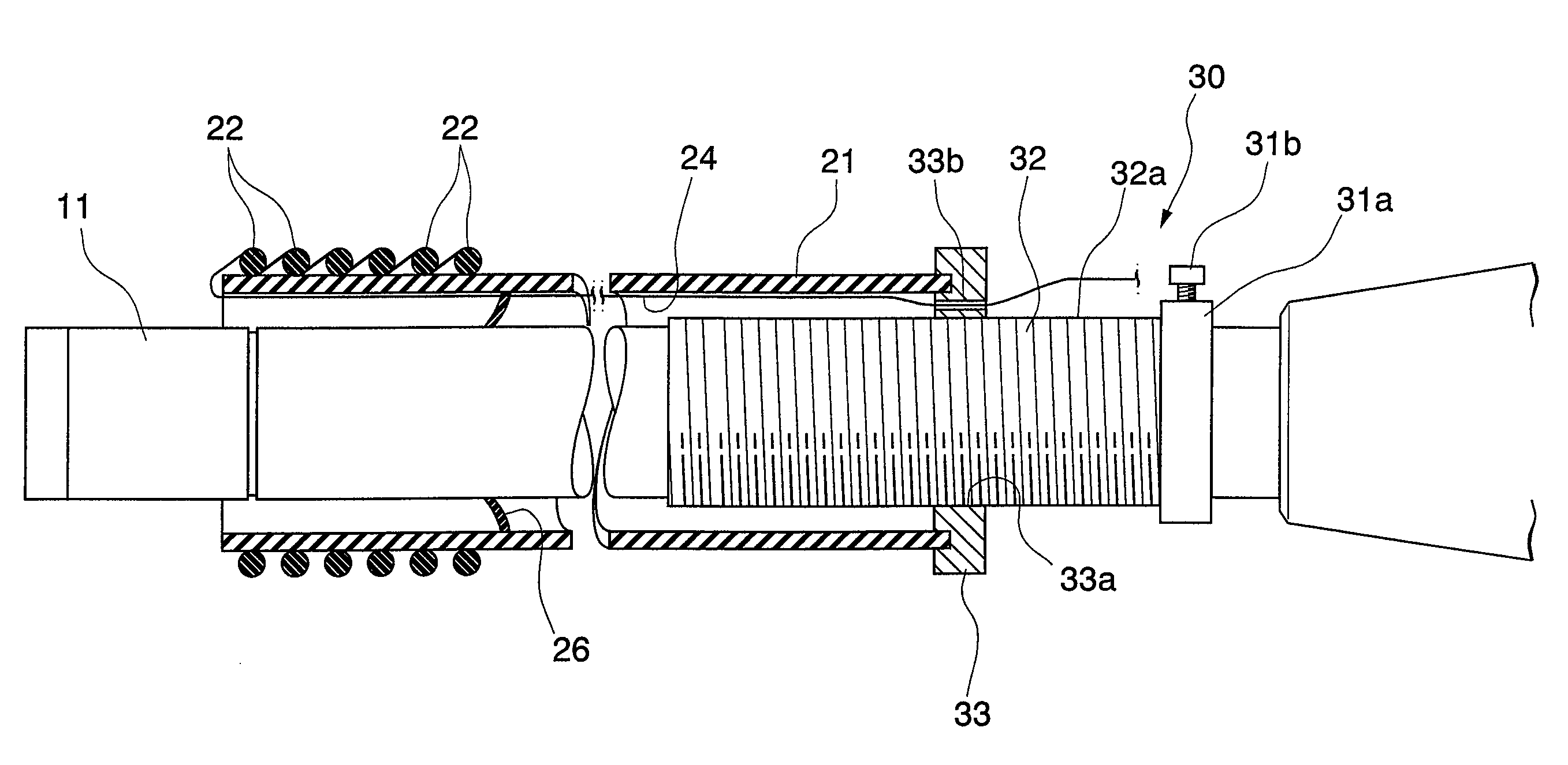
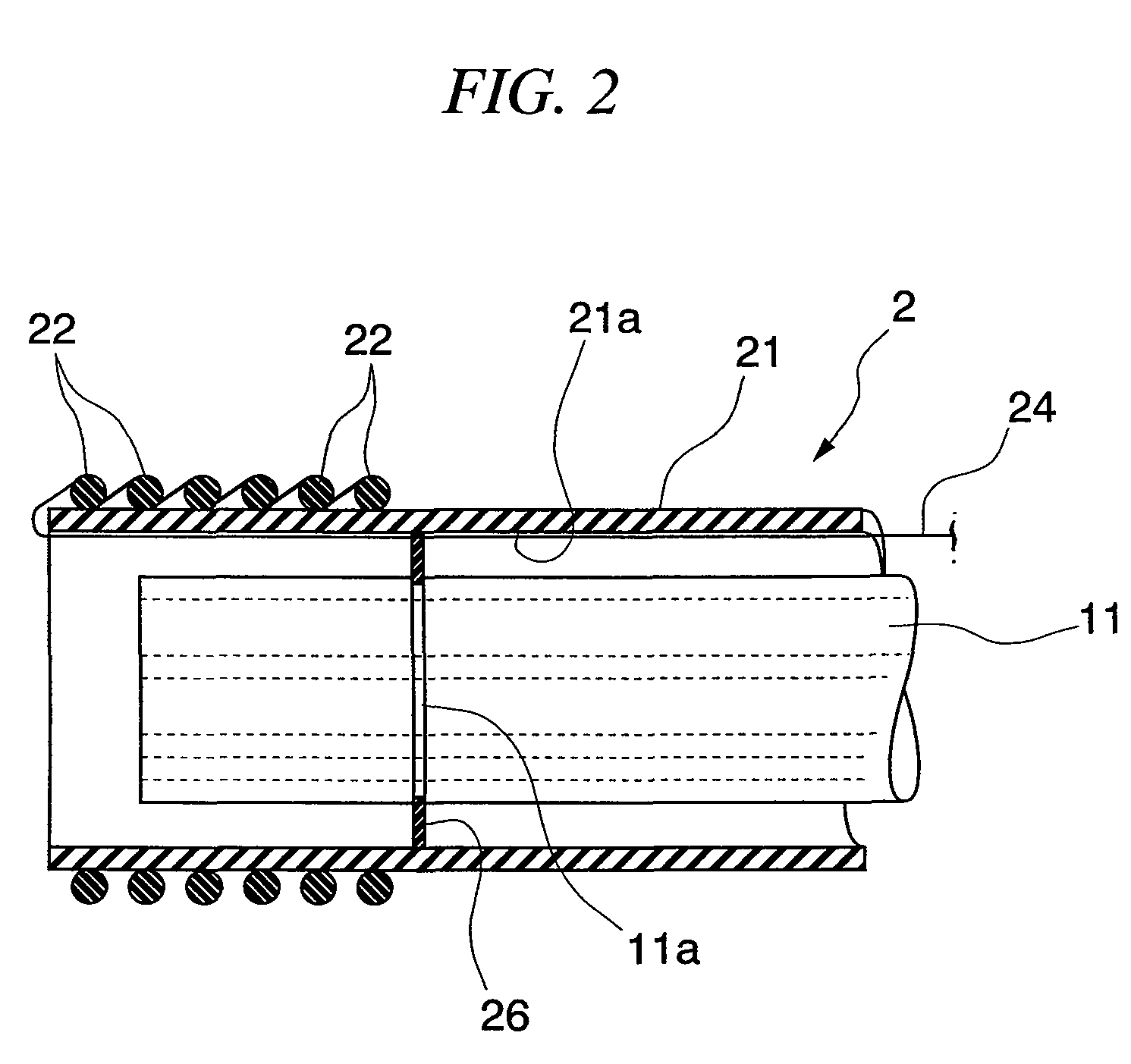
[0047]FIG. 1 to FIG. 6 show the embodiment of the invention, FIG. 1 is a configuration view of an endoscopic ligation system, and FIG. 2 is a sectional view showing chief parts of a ligation tool for endoscope.

[0048]As shown in FIG. 1, the endoscopic ligation system A is obtained by combining an endoscope 1 and a ligation tool for endoscope 2.

[0049]The endoscope 1 includes an insertion portion 11 having flexibility, an endoscope control portion 12 which is connected to a proximal end of the insertion portion 11 to bend and control a tip of the insertion portion 11, a plurality of channels 13 which is formed through the inside of the insertion portion 11, and permits forceps, etc. to be inserted therethrough.

[0050]The ligation tool for endoscope 2 includes an overtube 21 which permits the insertion portion 11 of the endoscope 1 to be inserted therethrough so as to advance a...


PUM


Abstract

A ligation tool for endoscope includes an overtube having an insertion lumen 21a made of a flexible material, which permits an insertion portion 11 of the endoscope to be inserted therethrough so as to advance and retreat, an O-ring 22 for ligation attached to a distal end of the overtube, and a operation wire 24 which is locked to the O-ring for ligation, has a distal portion extending to the proximal side of the overtube, and is operated to be pulled or pushed at its proximal side, thereby separating the O-ring for ligation from the tip of the overtube. According to this ligation tool for endoscope, time and effort taken to set the ligation tool for endoscope in the endoscope becomes unnecessary, a sufficient field of vision of the endoscope can be secured, and the curving performance of the tip of the insertion portion of the endoscope does not deteriorate. Furthermore, this ligation tool is also advantageous when endoscopic sclerotherapy is performed together.

Description

BACKGROUND OF THE INVENTION[0001]1. Field of the Invention[0002]The present invention relates to a ligation tool for endoscope and an endoscopic ligation system which ligates a varix formed in a body tissue, such as in an esophagus or a stomach.[0003]Priority is claimed on Japanese Patent Application No. 2007-257212, filed Oct. 1, 2007, the content of which is incorporated herein by reference.[0004]2. Description of Related Art[0005]Esophageal variceal ligation is known as a medical procedure for a varix formed in an esophagus or the stomach.[0006]In this esophageal variceal ligation, after a varix is suctioned by a tubular cap mounted to the tip of an endoscope, an O-ring for ligation mounted at the cap in advance is removed and is hung on a root portion of the varix, and the varix is mechanically ligated and eradicated by the rubber force of the O-ring for ligation.[0007]Meanwhile, conventionally, in order to perform the esophageal variceal ligation concretely, a ligation tool for...

Claims


Application Information

Patent Timeline
Patent Type & Authority Patents(United States)
IPC IPC(8): A61B17/10
CPCA61B1/00087A61B1/273A61B17/12013A61B17/3478A61B2017/00292A61B2017/00296A61B2017/00367A61B2017/00535A61B2017/12018A61B2017/347A61B17/32A61B17/122A61B17/12
Inventor GOTO, HIROAKI
Owner OLYMPUS CORP
Why Eureka
Try Eureka