Ti-based film forming method and storage medium

a technology of ti-based film and storage medium, which is applied in the direction of coating, process and machine control, instruments, etc., can solve the problems of affecting the appearance of the substrate, so as to suppress metal contamination or peeling, and reduce the adhesion of the alf-based material during cleaning

Active Publication Date: 2012-09-11
TOKYO ELECTRON LTD
View PDF12 Cites 0 Cited by
  • Summary
  • Abstract
  • Description
  • Claims
  • Application Information

AI Technical Summary

Benefits of technology

[0010]The object of the present invention is to provide a Ti-based film forming method capable of suppressing metal contamination or peeling-off of a pre-coated film of a shower head during formation of a Ti-based film on a substrate mounted on a mounting table by using a processing gas containing Ti, wherein the mounting table, at least a surface of which is made of a material containing Al, is provided in a chamber.
[0022]In accordance with the present invention, a pre-coated film is formed while a temperature of a mounting table is set to be lower than a temperature for forming a Ti-based film, preferably lower than or equal to 500° C., so that sublimation of an AlF-based material formed on the mounting table can be suppressed during cleaning. Accordingly, it is possible to reduce adhesion of the AlF-based material to a surface of a gas injecting member, and also possible to suppress metal contamination or peeling-off of the pre-coated film of the gas injecting member during film formation.
[0023]Further, by performing the pre-coating at a temperature lower than a conventional temperature condition, even when the surface of the gas injecting member is made of Ni, the reaction between Ni and Ti contained in a processing gas can be suppressed. As a result, it is possible to suppress the generation of particles caused by formation of an NiTi layer or the change in color and quality of Ni.

Problems solved by technology

The AlF-based material, however, has lower adhesivity.
Therefore, even if a Ti film is pre-coated on the AlF-based material, the pre-coated film may be peeled off during a film forming process, which may cause generation of particles.
In that case, the wafer surface may be contaminated by the AlF-based material released into the film forming gas.
The NiTi may be incorporated into the pre-coated film and be eluted during the film forming process, which may lead to contamination of the wafer surface.

Method used


Image

  • Ti-based film forming method and storage medium
  • Ti-based film forming method and storage medium
  • Ti-based film forming method and storage medium

Examples


Embodiment Construction

[0036]Embodiments of the present invention will be described with reference to the accompanying drawings.

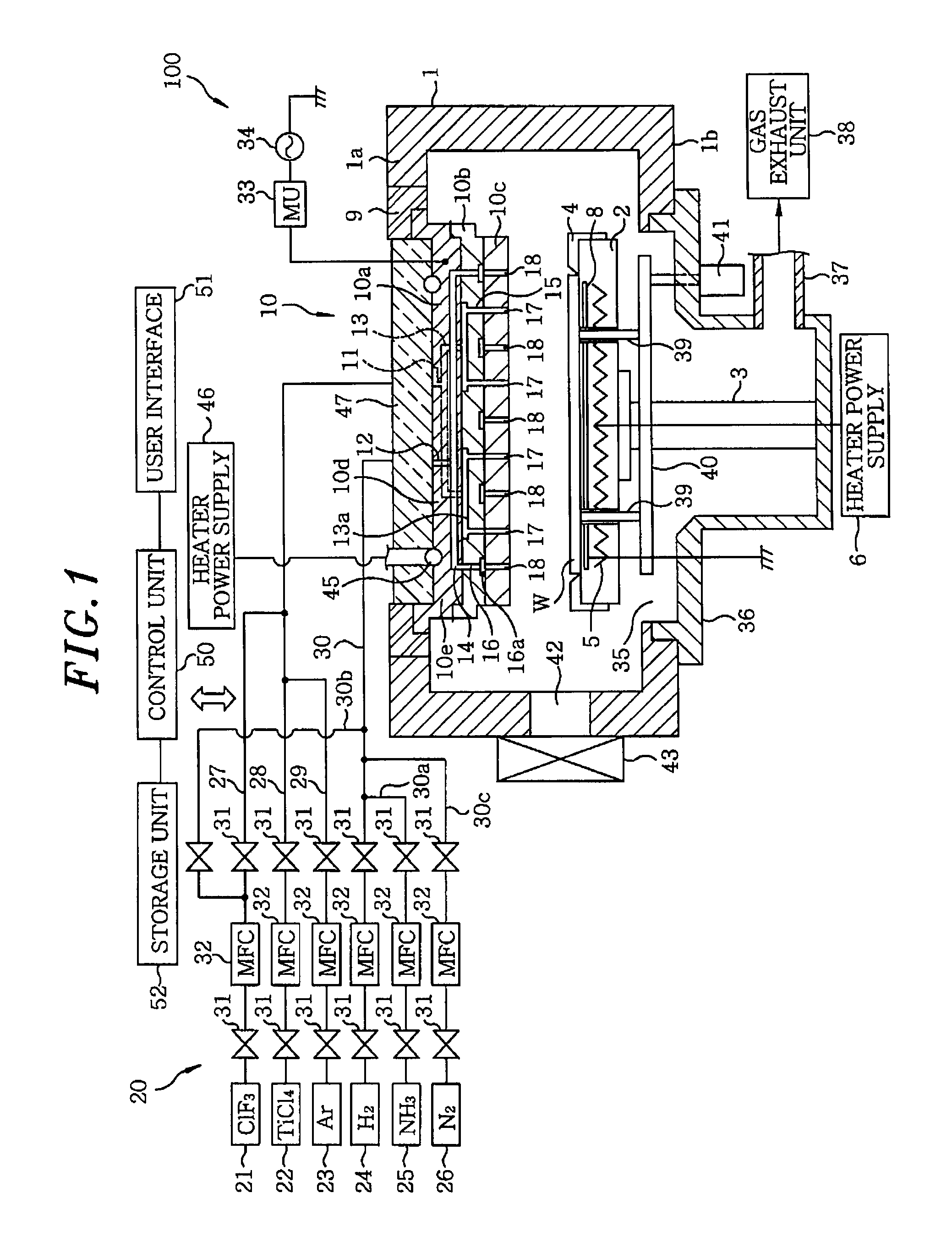
[0037]FIG. 1 is a schematic cross sectional view showing an example of a Ti film forming apparatus used for executing a Ti film forming method in accordance with an embodiment of the present invention. The Ti film forming apparatus 100 is configured as a plasma CVD film forming apparatus for performing CVD film formation by generating a plasma through forming a high frequency electric field between parallel plate electrodes.

[0038]The Ti film forming apparatus 100 includes a substantially cylindrical chamber 1. A susceptor 2 made of AlN is provided in the chamber 1 to horizontally support a wafer W serving as a substrate to be processed. The susceptor 2 is supported by a cylindrical supporting member 3 installed at a position in a central bottom portion thereof. A guide ring 4 for guiding the wafer W is installed at an outer edge portion of the susceptor 2. Further, a heater 5 is ...


PUM

PropertyMeasurementUnit
temperatureaaaaaaaaaa

Abstract

A Ti-based film forming method includes a step (step 1) of cleaning inside a chamber by introducing a cleaning gas containing fluorine into the chamber in a state where a wafer W is not provided on a susceptor; a step (step 2) of heating the susceptor in a state where the wafer W is not provided on the susceptor, injecting a processing gas containing Ti from a shower head into the chamber, and forming a pre-coated film at least on the surface of the shower head; and a step (step 3) of mounting the wafer W on the susceptor 2 in a state where the susceptor is heated, supplying a processing gas into the chamber 1 and forming a Ti-based film on the wafer W. The pre-coated film forming step is performed at a temperature lower than that in the film forming step.

Description

[0001]This application is a Continuation Application of PCT International Application No. PCT / JP2007 / 070266 filed on Oct. 17, 2007, which designated the United States.FIELD OF THE INVENTION[0002]The present invention relates to a Ti-based film forming method for forming a film containing a Ti element (Ti-based film) on a surface of a substrate to be processed disposed on a mounting table in a chamber by injecting a processing gas containing Ti through a shower head into the chamber and a storage medium which stores therein a program for executing the Ti-based film forming method.BACKGROUND OF THE INVENTION[0003]In a manufacture of a semiconductor device, to meet recent demands for higher density and higher integration degree, a circuit arrangement tends to have a multilayer interconnection structure. Therefore, a technique that forms a buried portion for electrically connecting layers to each other through a contact hole for connecting a lower semiconductor substrate to an upper wir...

Claims


Application Information

Patent Timeline
Patent Type & Authority Patents(United States)
IPC IPC(8): C23C16/06
CPCC23C16/14C23C16/4404H01L21/28556C23C16/45565C23C16/56C23C16/4405C23C16/44H01L21/28H01L21/285
Inventor NARUSHIMA, KENSAKUWAKABAYASHI, SATOSHITAKAYAMA, TAKAMITSU
Owner TOKYO ELECTRON LTD
Why Eureka
Try Eureka