Specialized processing block for programmable logic device

a technology of programmable logic and processing blocks, applied in the field of special processing blocks, can solve the problems of increasing complexity of applications for which plds are used, limited rounding limited saturation capabilities of known dsp blocks, so as to achieve the effect of improving rounding and saturation capabilities

Active Publication Date: 2012-09-11
TAHOE RES LTD
View PDF377 Cites 14 Cited by
  • Summary
  • Abstract
  • Description
  • Claims
  • Application Information

AI Technical Summary

Benefits of technology

[0008]The present invention relates to specialized processing blocks for PLDs wherein the specialized processing blocks have improved rounding and saturation capabilities.
[0009]The specialized processing block with which the invention may be used preferably includes a plurality of fundamental processing units instead of discrete multipliers. Each fundamental processing unit preferably includes the equivalent of at least two multipliers and logic to sum the partial products of all of the at least two multipliers. As a result, the sums of the all of the multiplications are computed in a single step, rather than summing the partial products of each multiplier to form individual products and then summing those products. Such a fundamental processing unit can be constructed with an area smaller than that of the individual multipliers and adders. If a single multiplication is required to be performed, one of the multipliers in the fundamental processing unit is used, while the inputs to the other(s) are zeroed out. Nevertheless, because the provision of the fundamental processing unit reduces the area of the specialized processing block, efficiency is improved.
[0013]The flexible rounding circuitry according to the invention preferably allows the user to select between rounding to the nearest integer and rounding to the nearest even. As is known, rounding to the nearest even operates identically to rounding to the nearest integer, except when the remainder is exactly equal to one-half. In rounding to the nearest integer, when the remainder is exactly equal to one-half, the result always is rounded up to the next integer. In rounding to the nearest even, when the remainder is exactly equal to one-half, the result is rounded up if the next integer is even, but rounded down if the next integer is odd. The flexible rounding circuitry preferably also allows the user to select the bit position of the result at which rounding takes place. The location of the flexible rounding circuitry within the specialized processing block preferably also is selectable so that critical timing paths are not affected unnecessarily by rounding operations.
[0014]The flexible saturation circuitry according to the invention preferably allows the user to select between symmetrical and asymmetrical clipping of the result. As is known, in certain types of numerical representations, such as one's-complement representations, a numerical variable that ranges up to 2n−1 ranges down to −(2n−1), and thus ranges symmetrically. However, in other types of numerical representations, such as two's-complement representations, a numerical variable that ranges up to 2n−1 ranges down to −(2n), and thus ranges asymmetrically. In clipping an arithmetic result, it may be desirable for the result to be clipped symmetrically regardless of the type of representation, and the present invention preferably allows the user to select such a result. The flexible saturation circuitry preferably also allows the user to select the bit position of the result at which clipping takes place. The location of the flexible saturation circuitry within the specialized processing block preferably also is selectable so that critical timing paths are not affected unnecessarily by clipping operations.

Problems solved by technology

As applications for which PLDs are used increase in complexity, it has become more common to design PLDs to include specialized processing blocks in addition to blocks of generic programmable logic resources.
However, known DSP blocks, including that provided in the aforementioned STRATIX® II PLD, have limited rounding capabilities.
However, saturation capabilities of known DSP blocks also are limited.

Method used


Image

  • Specialized processing block for programmable logic device
  • Specialized processing block for programmable logic device
  • Specialized processing block for programmable logic device

Examples


embodiment 10

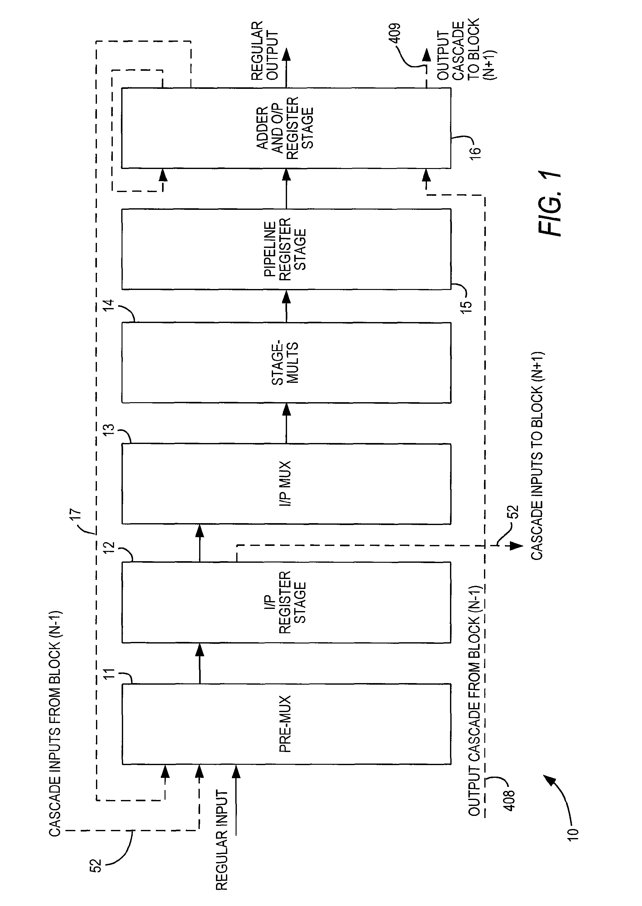
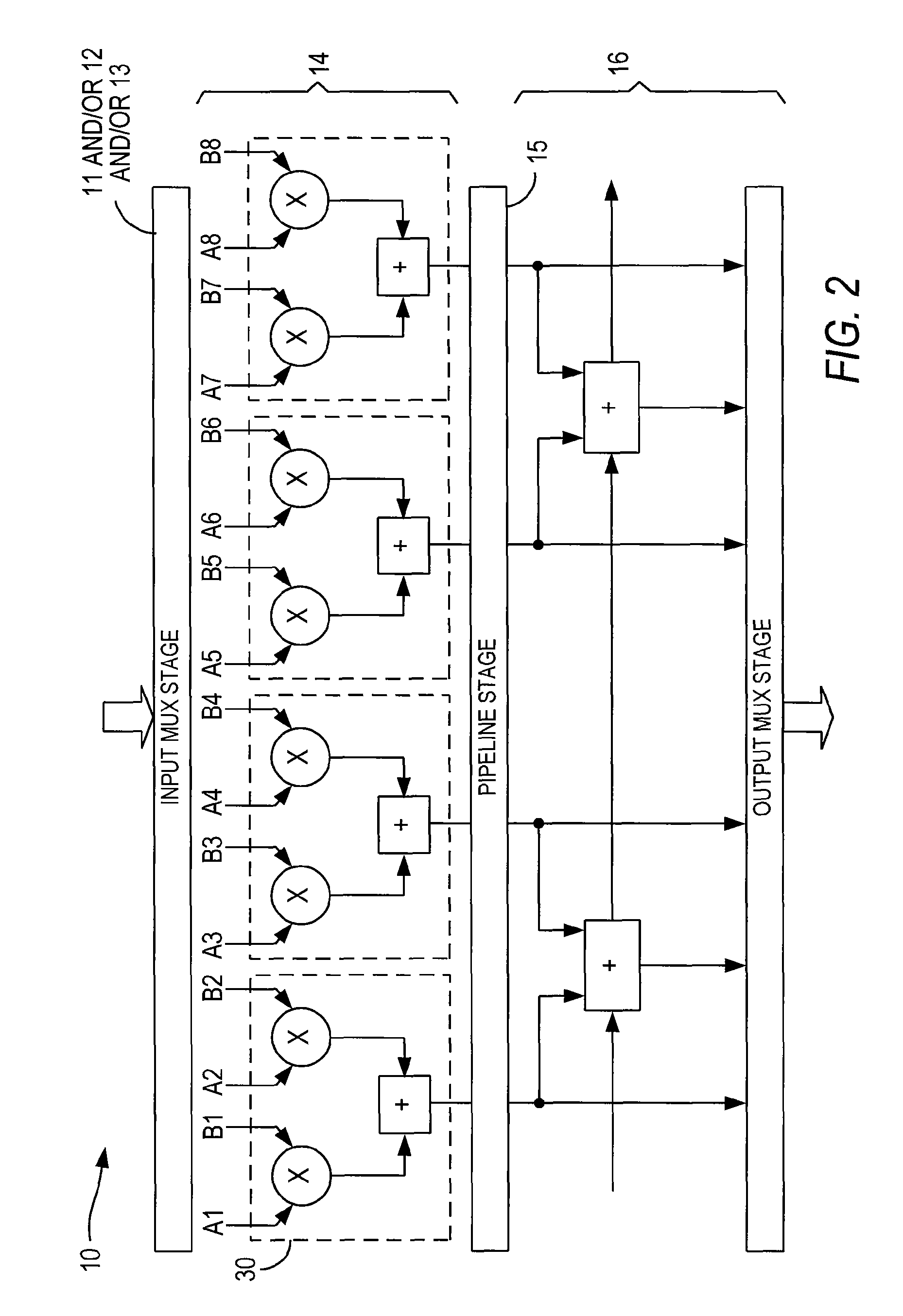
[0040]FIG. 1 shows a high-level diagram of one preferred embodiment 10 of a specialized processing block according to the invention, while FIG. 2 is a functional diagram of the same embodiment 10.

[0041]As seen in FIG. 1, specialized processing block 10 includes optional input pre-MUX stage 11, optional input register stage 12, optional input multiplexing stage 13, multiplication stage 14, optional pipeline register stage 15 and adder / output stage 16.

[0042]The function of input pre-MUX stage 11, if provided, is to format the regular inputs, loopback inputs and cascade inputs (see below) into a form suitable for registering.

[0043]Regular inputs do not require any specific formatting. Cascade inputs may be a one-register delayed version of a previous input, and therefore may need formatting accordingly. However, such formatting also can be done in programmable logic of the programmable logic device of which specialized processing block 10 is a part, so if formatting of cascade inputs i...

embodiment 70

[0077]The result, RNDSEL, is used, after the ORing of all RNDSEL bits as described above, as the control bit to select between rounded and unrounded values as shown, e.g., in FIGS. 7 and 8. In the embodiment 70 of FIG. 7, which may be programmably implemented in specialized processing block 10, the output of adder 71 is input to both rounding logic 60 and further adder 72. The output of rounding logic 60 is also input to adder 72, and controls whether or not adder 72 adds 1 to the output of adder 71. Because these rounding operations, as well as saturation operations in saturation logic 73, are in a critical path between registers 74, 75, the rounding and saturation operations must be completed within one clock cycle. This limits the maximum clock speed to one in which the rounding and saturation operations can be completed.

embodiment 80

[0078]Therefore, in embodiment 80 of FIG. 8, which may be programmably implemented in specialized processing block 10, instead of waiting for rounding logic 60 before performing addition 82, addition 71 and addition 82 are carried out simultaneously and the result of rounding logic 60 is used to control multiplexer 81, which selects between adders 71, 81. This look-ahead rounding decreases the time needed to perform rounding operations, and therefore increases the maximum permissible clock speed.

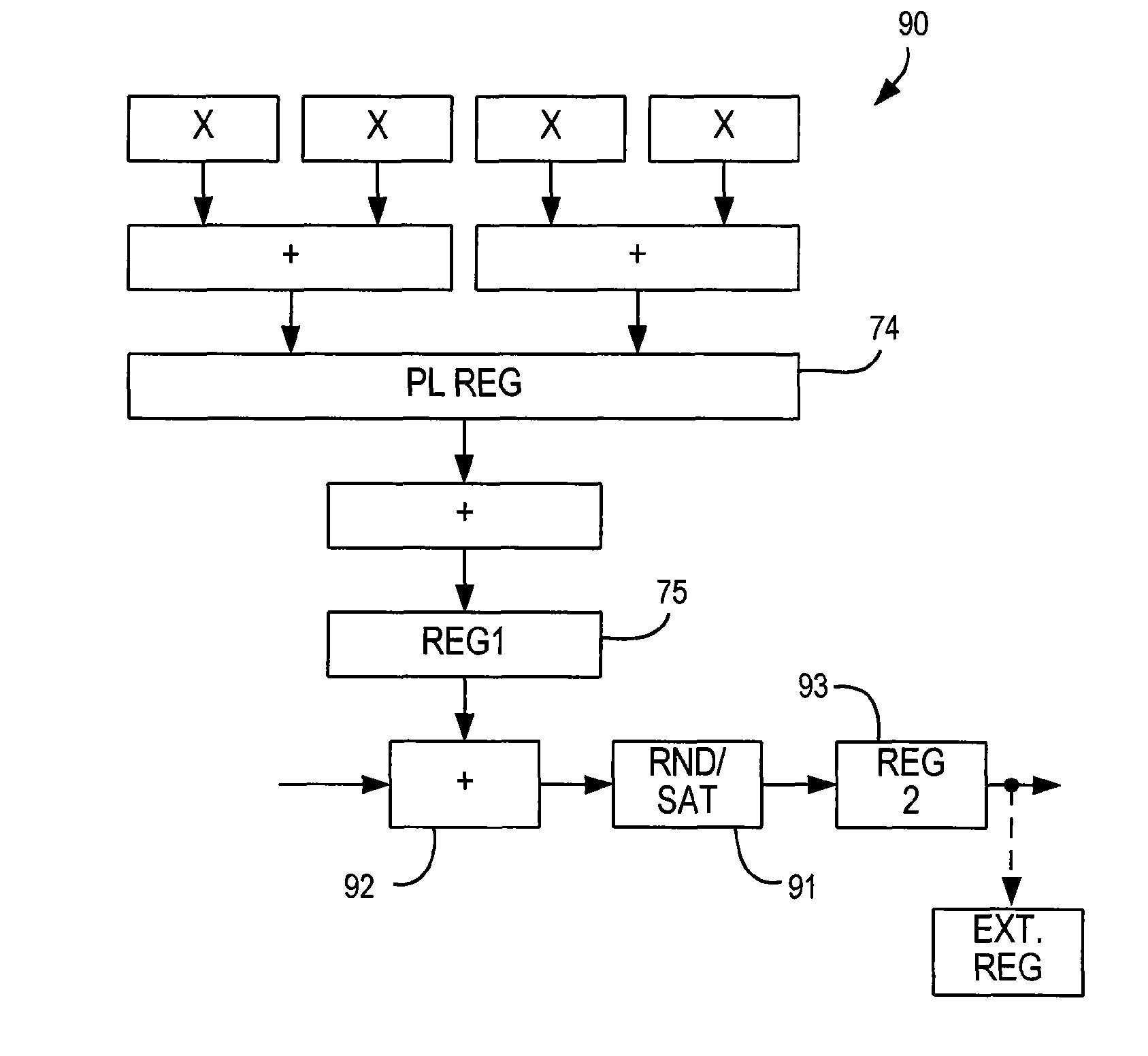
[0079]Similar clocking issues come into play when specialized processing block 10 is used in output cascade mode with another specialized processing block 10. As seen in embodiment 90 of FIG. 9, which may be programmably implemented in specialized processing block 10, the rounding and saturation circuitry 91 is located between cascade adder 92 and register 93. Once again, that places it in the critical path for register timing. Therefore, in the embodiment 100 shown in FIG. 10, which may be ...


PUM


Abstract

A specialized processing block for a programmable logic device includes circuitry for performing multiplications and sums thereof, as well as circuitry for rounding the result. The rounding circuitry can selectably perform round-to-nearest and round-to-nearest-even operations. In addition, the bit position at which rounding occurs is preferably selectable. The specialized processing block preferably also includes saturation circuitry to prevent overflows and underflows, and the bit position at which saturation occurs also preferably is selectable. The selectability of both the rounding and saturation positions provides control of the output data word width. The rounding and saturation circuitry may be selectably located in different positions based on timing needs. Similarly, rounding may be speeded up using a look-ahead mode in which both rounded and unrounded results are computed in parallel, with the rounding logic selecting between those results.

Description

CROSS REFERENCE TO RELATED APPLICATION[0001]This claims the benefit of commonly-assigned U.S. Provisional Patent Application No. 60 / 771,989, filed Feb. 9, 2006, which is hereby incorporated by reference herein in its entirety.BACKGROUND OF THE INVENTION[0002]This invention relates to programmable logic devices (PLDs), and, more particularly, to specialized processing blocks which may be included in such devices.[0003]As applications for which PLDs are used increase in complexity, it has become more common to design PLDs to include specialized processing blocks in addition to blocks of generic programmable logic resources. Such specialized processing blocks may include a concentration of circuitry on a PLD that has been partly or fully hardwired to perform one or more specific tasks, such as a logical or a mathematical operation. A specialized processing block may also contain one or more specialized structures, such as an array of configurable memory elements. Examples of structures...

Claims


Application Information

Patent Timeline
Patent Type & Authority Patents(United States)
IPC IPC(8): G06F7/38H03K19/177H03K19/173
CPCG06F7/49921G06F7/49947G06F7/49963G06F7/5443
Inventor LEE, KWAN YEE MARTINLANGHAMMER, MARTINLIN, YI-WENNGUYEN, TRIET M.
Owner TAHOE RES LTD
Why Eureka
Try Eureka