Rack for transportation and display of plants

a plant transportation and plant technology, applied in the field can solve the problems of conflicting design requirements that have not been adequately addressed, difficult or even impossible to water or otherwise reach the innermost, and often neglected formers, etc., and achieve the effect of reducing and increasing the number of plant storage racks

Inactive Publication Date: 2012-09-18
VANDERHOEK WIEBE S +1
View PDF76 Cites 47 Cited by
  • Summary
  • Abstract
  • Description
  • Claims
  • Application Information

AI Technical Summary

Benefits of technology

[0021]The channel members may comprise flange portions that project inwardly proximate middle areas of said channel members so as to define said upper and lower runs thereof. The means for tilting the trays in the deployed position may further comprise a pair of pivot projections at sides of said trays that engage said lower runs of said guide channels at locations intermediate front and rear edges of said trays, so as to support middle portions of said trays while said projections at said rearward edges of said trays are received in said upper runs of said guide channels. The pivot projections may comprise rod ends that project laterally from sides of the trays, and the guide channels may further comprise stop walls formed at outer ends of said lower runs, that contact said pivot projections on said trays so as to prevent said trays from sliding out of said assembly when in said downwardly angled orientation. The guide channels may further comprise layers of low friction material that are mounted in said lower runs of said guide channels.
[0022]The rack assembly may further comprise at least one stabilizer assembly that prevents tipping of the rack assembly when the trays are in the deployed position. The stabilizer assembly may comprise a tube member that is mounted to the mobile frame, first and second shaft members that are received in the tube member so as to be selectively extensible on opposite sides of the frame, and first and second stabilizer legs mounted on outer ends of the shaft members that are selectively rotatable to be positioned proximate a ground surface when the shaft members are extended on opposite sides of the frame.

Problems solved by technology

Plant transport carts therefore face conflicting design requirements that have not been adequately addressed by the prior art.
At the retail location, on the other hand, it is important for the customers to be able to see and reach the individual plants, which is not possible with the shelves positioned closely atop one another.
Moreover, the plants require watering and other care while on display, which may be a period of days or even weeks; however, with the shelves placed closely together it is difficult or even impossible to water or otherwise reach the innermost plants, at least without damaging those at the outer edges of the trays, so that the former are frequently neglected and become unsellable.
However, spacing the racks farther apart reduces the number of plants that can be carried during transportation.
Although this arrangement allows the trays to be spread apart vertically once the rack has been delivered to the retail store, it necessitates removing several of the trays to create the space between the others; storage of the removed trays then becomes problematic, and the plants thereon must be displayed separately from those in the rack.
Other racks have been configured to allow the trays to be tilted for easier viewing, but this alone does little to address the issues of spacing and efficient storage of the plants during transportation.
Safety is also a significant factor, since the racks are very heavy, especially when fully loaded, and could cause injury to customers or store personnel if they were to topple over during use.
A concurrent requirement is that the racks must be comparatively economical to produce, since even a modestly-sized grower / supplier needs a great many racks, representing a significant capital expense.

Method used


Image

  • Rack for transportation and display of plants
  • Rack for transportation and display of plants
  • Rack for transportation and display of plants

Examples


Embodiment Construction

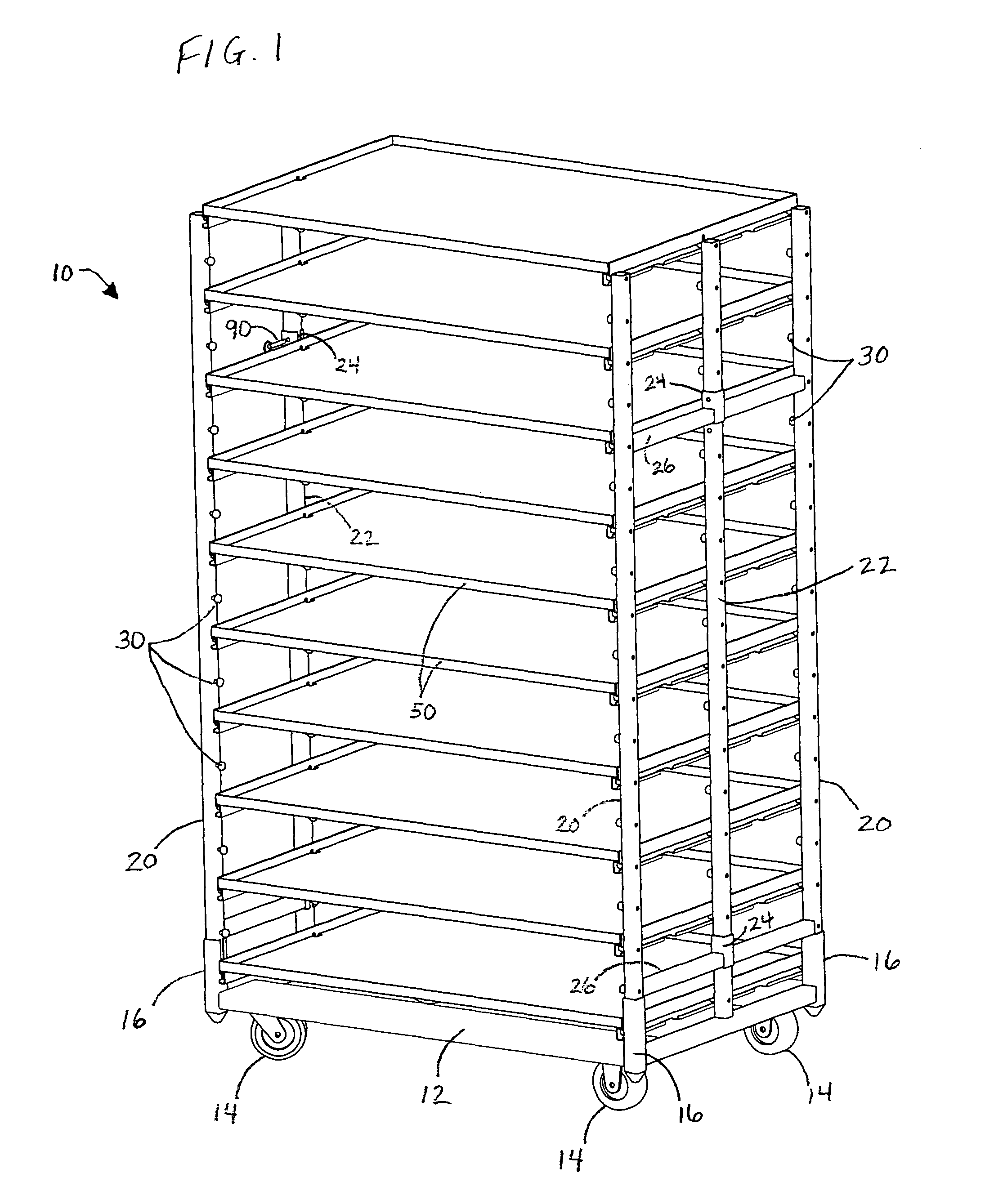
[0049]FIG. 1 shows a plant transportation and storage rack assembly 10 in accordance with the present invention. As can be seen, the assembly includes a rectangular base frame 12 that is supported for rolling movement by casters 14. The frame includes vertically-aligned sockets 16 at each of its four corners (three only being visible in FIG. 1), which are suitably formed of square-section metal tubing welded to the rails / cross-members of the base frame.

[0050]The sockets 16 each receive a vertical stanchion or post members 18 in removable, sliding engagement therewith, the post members suitably being formed of square-section metal tubing dimensioned to fit closely within the sockets. The post members are each substantially identical in construction so that they fit interchangeably within the sockets 16, thereby facilitating knock-down and reassembly of the rack.

[0051]The stationary post members 20 are mounted in parallel, spaced-apart pairs at each end of the rack assembly. A third, ...


PUM


Abstract

A rack assembly for transportation and display of potted plants and similar articles. The rack includes vertical supports, and a plurality of trays that are slidingly supported on the posts. The trays are extensible from a retracted position in which the trays are arranged in compact, vertically spaced relationship for transportation, to a deployed position in which the trays extend on opposite sides in an alternating arrangement with increased vertical spacing, and are tilted to a downwardly angled orientation so that the plants can be readily viewed and accessed by customers and other personnel. The posts and trays are mounted on a mobile frame that includes stabilizer legs which prevent the assembly from tipping when the trays are in the deployed position. The posts and trays are removable from the frame, and can be broken down for storage.

Description

RELATED APPLICATIONS[0001]This application is a continuation-in-part application of abandoned U.S. non-provisional patent application Ser. No. 12 / 226,085, entitled “Rack for Transportation and Display of Plants”, filed Oct. 21, 2008, which claims the benefit of U.S. provisional patent application Ser. No. 60 / 790,201, entitled “Transportation and Display Rack for Bedding Plants”, filed Apr. 7, 2006.BACKGROUND[0002]a. Field of the Invention[0003]The present invention relates generally to racks for holding and displaying plants, and, more particularly, to a rack for potted plants having trays that retract to a compact form for transportation and that extend and tilt for display and accessibility of the plants at a retail location.[0004]b. Related Art[0005]Bedding plants (e.g., flowers, vegetables, herbs and so forth) are commonly placed on racks for transportation from the grower's facility to the store or other retail location. Conventionally, the racks comprise a wheeled frame or bas...

Claims


Application Information

Patent Timeline
Patent Type & Authority Patents(United States)
IPC IPC(8): A47B47/00A47B57/04
CPCA01G9/143A47F7/0078A47F5/0081Y10T16/1853Y02A40/25
Inventor VANDERHOEK, WIEBE S.VAN WINGERDEN, MIKE
Owner VANDERHOEK WIEBE S
Why Eureka
Try Eureka