
Carrier apparatus for pneumatic tube delivery system

Active Publication Date: 2012-09-18
PEVCO SYST INT
View PDF29 Cites 23 Cited by
  • Summary
  • Abstract
  • Description
  • Claims
  • Application Information

AI Technical Summary

Benefits of technology

[0013]It is an object of the present invention to provide a carrier apparatus that enables safe and reliable use in a pneumatic tube delivery system.
[0014]It is another object of the present invention to provide a carrier apparatus whose structure preserves reliable payload containment and accommodates sure, convenient handling by a user.

Problems solved by technology

The network of tubular conduits can become quite complex even in modest sized facilities, since delivery access between all combinations of user outlets is often required.
There are numerous challenges to maintaining efficient operation of pneumatic tube delivery systems, especially those deployed in such heavy-use, critical settings.
A number of notable challenges pertain to the structure and form of the carrier employed in the system.
In that event, technicians would need ample time to carry out the tedious task of first locating the stuck carrier, then accessing the carrier by disassembling or even cutting the conduit segment in question, before restoring the conduit segment for use upon extrication of the carrier.
Reliably ensuring that the carriers are properly closed for transport is another constant challenge.
Because the carrier travels through confined spaces at high speeds, being all the while subject to forceful impact and abrupt changes of direction, there is much to potentially disturb and jar a carrier's closure mechanism loose.
For example, the snap-buckle type latching mechanisms used in many carriers heretofore known are prone to spring free when acute incidental contact or a sudden shift in direction disrupt and overcome the mechanism's closure bias.
Intervening hardware like transitional / diverter units also present potential snag hazards for such latching mechanisms.
Other challenges derive from the fact that the oft-used carrier must be versatile enough to carry a wide range of payloads.
Since their maximum transverse (diametric) dimension is limited by the conduit size employed in the given system, carriers in most systems are necessarily elongated and bulky in form.
Yet, their high speed travel through confining tubular conduits precludes the use of external handle attachments to facilitate handling.
Consequently, carriers heretofore known in the art tend to be difficult to firmly grasp and safely manipulate with one hand.
Users in these settings can ill afford to mishandle carriers.
Nor can they afford the risks of the carriers tipping or rolling away (and perhaps off a table surface) when they are momentarily set aside during user handling.
Yet no adequate safeguard measures are provided by carriers heretofore known in the art.
Still another challenge to efficient, reliable system operation is the carriers' general durability in the face of daily repetitive use.
In addition to the normal incidental contact encountered during travel through the conduit network and mechanical handling such as at intervening transfer points, carriers typically encounter sharp impact each time they arrive at their destinations.
The shock of this impact, especially when repeated over and again with regular use, wears on the carrier and potentially leads to premature stress failure over time at its axial ends and elsewhere.
Over time and with repeated use, glide bands become worn down causing their friction reducing and cushioning properties to diminish.
This approach makes later removal of the bands for replacement difficult since the adhesive, in order to maintain attachment to the carrier during transport, must be very strong.
These and other challenges are not adequately met by carriers heretofore known in the art.

Method used


Image

  • Carrier apparatus for pneumatic tube delivery system
  • Carrier apparatus for pneumatic tube delivery system
  • Carrier apparatus for pneumatic tube delivery system

Examples


Embodiment Construction

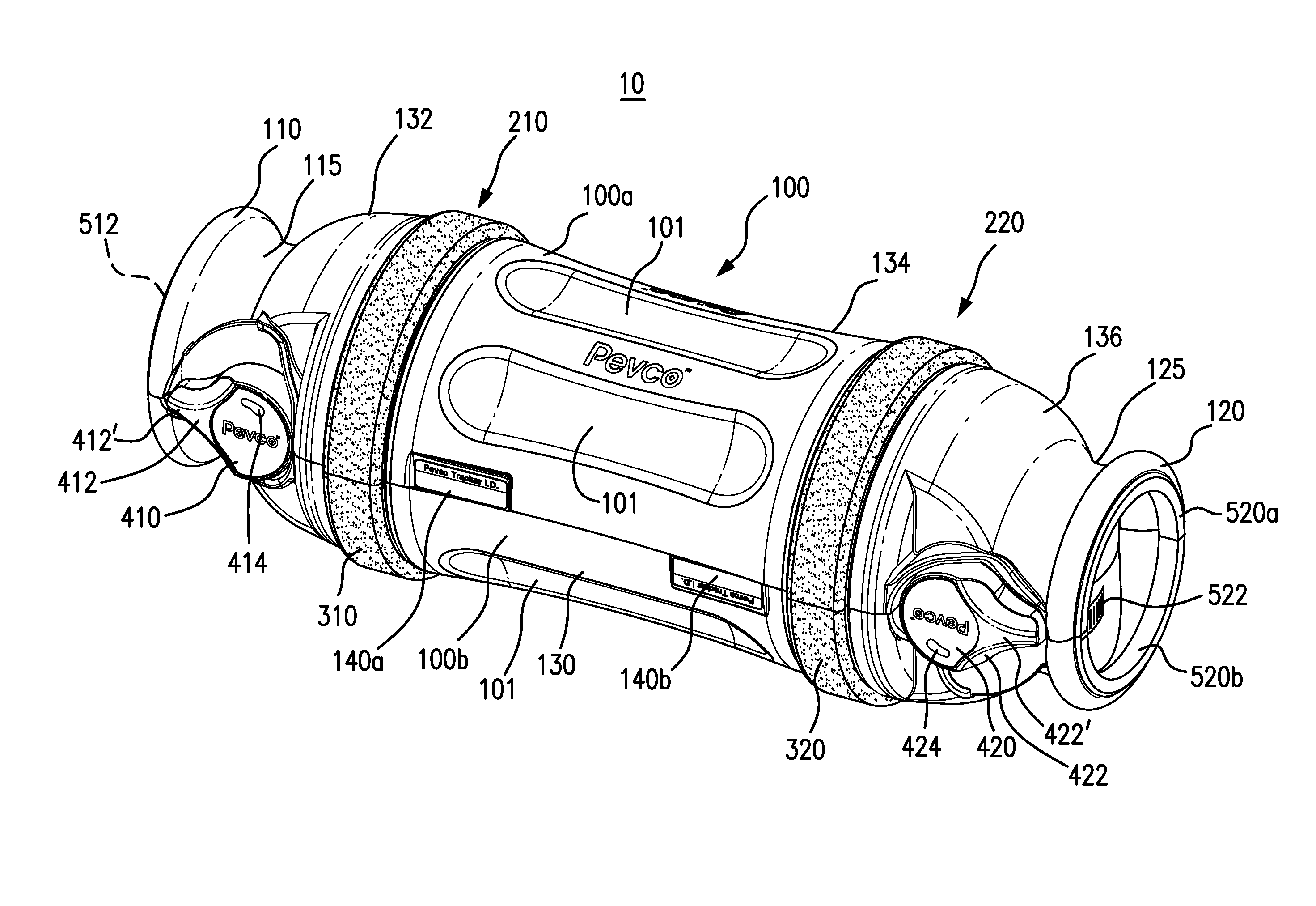
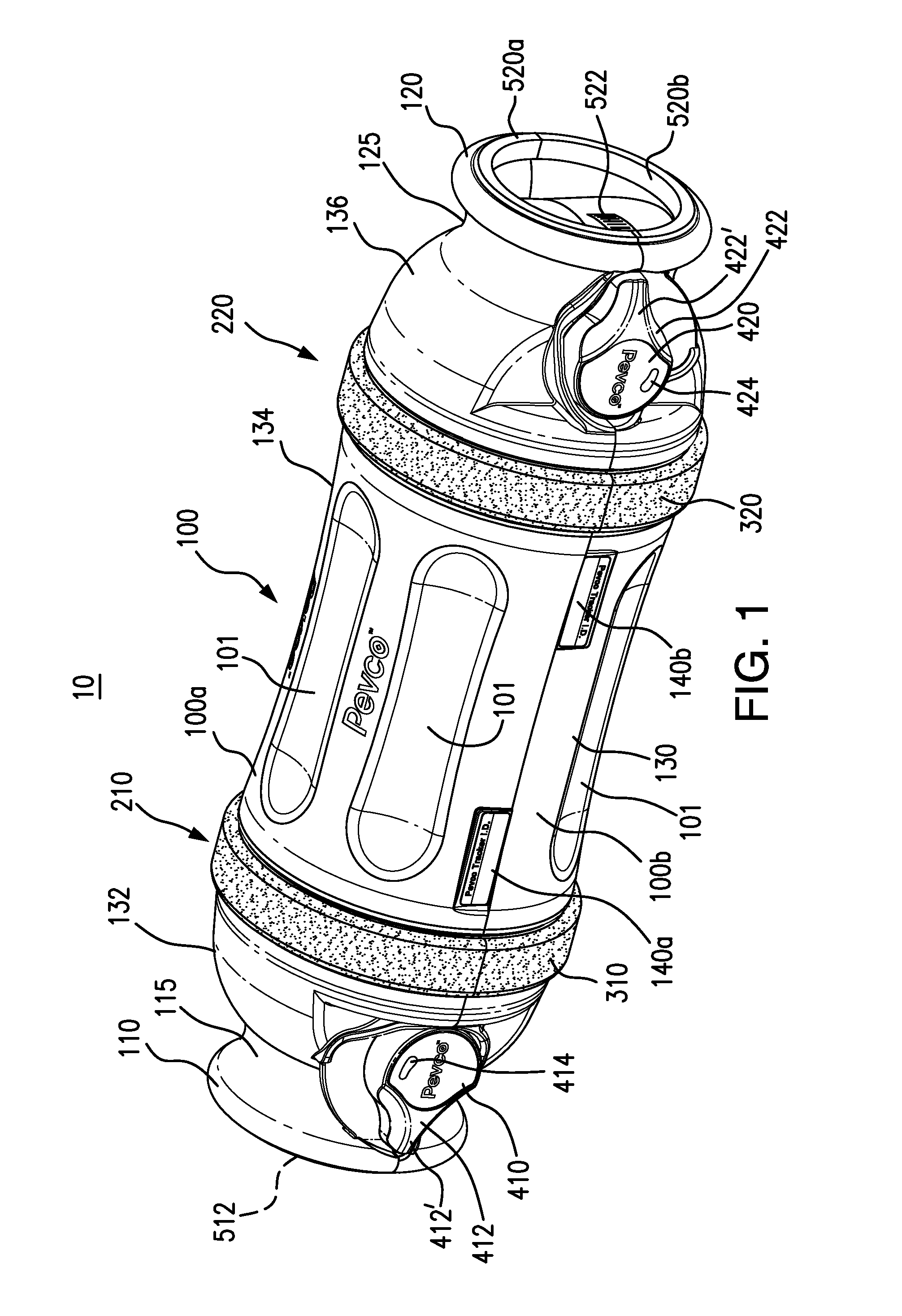
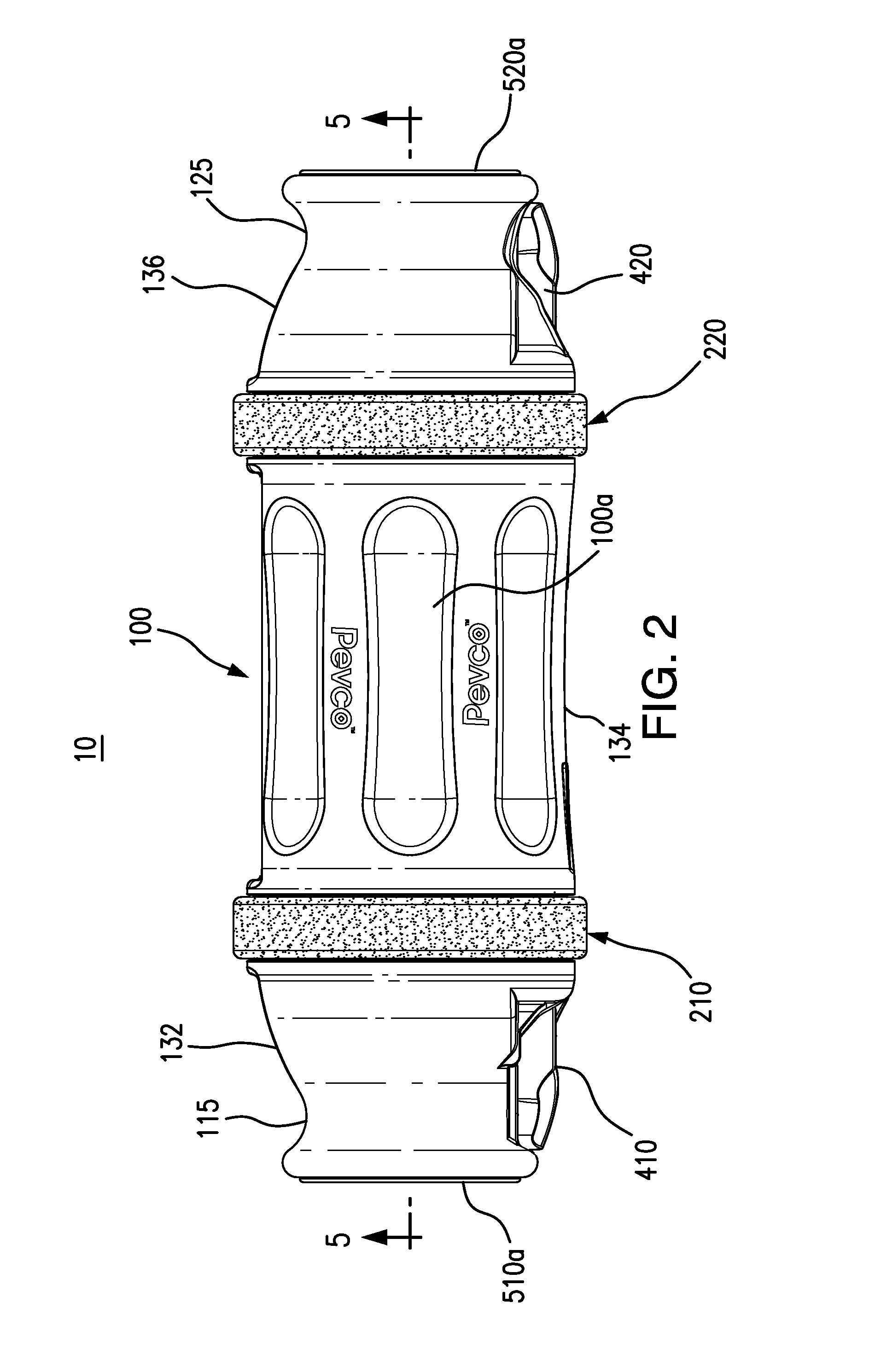
[0038]Referring now to FIGS. 1-8, there are shown various views of a carrier apparatus 10 formed in accordance with an exemplary embodiment of the present invention. In FIGS. 1-8, carrier apparatus 10 is shown in its closed and fully latched configuration, ready for transport through a pneumatic tube delivery system (not shown).

[0039]Carrier apparatus 10 is formed with a housing 100 whose capsule-like structure encloses an internal carrying compartment for various payloads. Housing 100 may be formed of any suitable material known in the art. Because carrier apparatus 10 serves as a transport capsule propelled at high speeds through an extensive network of chutes / tubular conduits, however, housing 100 is formed of a material having the strength, rigidity, density, hardness, and other such material properties sufficient to withstand the structural / inertial punishment encountered during use and protect the payload against the same. In the illustrated embodiment, for example, housing 10...


PUM


Abstract

A carrier apparatus is provided for transport through a pneumatic tube delivery system. The carrier apparatus comprises a housing contoured with forward and aft portions and an axially extended body portion disposed therebetween. The housing includes at least first and second separable sections enclosing a carrying compartment. At least a pair of retaining assemblies are detachably coupled to the housing, with each retaining assembly encircling the housing's body portion to couple the first and second housing sections for angular displacement one relative to the other between open and closed configurations. Each of the retaining assemblies includes a glide band portion disposed to protrude radially from the housing in the closed configuration for slidably engaging an inner wall surface of a pneumatic delivery tube. At least one latch assembly is coupled to releasably lock the housing sections in the closed configuration.

Description

BACKGROUND OF THE INVENTION[0001]The present invention is generally directed to a carrier apparatus for a pneumatic tube delivery system. More specifically, the subject carrier apparatus is one which safely and securely transports various items through the tubular conduits of a given pneumatic tube delivery system. The subject carrier apparatus provides simple yet durable structure that facilitates safe, convenient handling and use.[0002]Pneumatic tube delivery systems are widely used in various institutions. The system is implemented in different forms depending on the nature of the operations and transactions carried out at a particular facility. Nonetheless, the systems invariably share certain basic components. First, a network of tubular conduits is established throughout the facility, branching out to various user outlets connected to respective send / receive workstations, or portals. Items of interest are then transported between user outlets via the network of delivery tubes ...

Claims


Application Information

Patent Timeline
IPC IPC(8): B65G51/06
CPCB65G51/06B65G51/42
Inventor MACLEAN-BLEVINS, MARKDAHL, STEVENVALERINO, SR., FREDERICK M.
Owner PEVCO SYST INT
Learn More