Low-profile microneedle array applicator

a microneedle array and applicator technology, applied in the field of low-profile microneedle array applicators, can solve the problems of limited number of molecules with demonstrated, and achieve the effects of low cost, simple use, and convenient handling

Active Publication Date: 2012-09-18
KINDEVA DRUG DELIVERY LP
View PDF155 Cites 57 Cited by
  • Summary
  • Abstract
  • Description
  • Claims
  • Application Information

AI Technical Summary

Benefits of technology

[0006]The present invention provides an application device for applying a microneedle device to a skin surface comprising a flexible sheet having a raised central area wherein motion of the raised central area in a direction perpendicular to the plane of the flexible sheet drives the microneedle device against the skin. This can provide an applicator that is easy to handle, simple to use, low cost, and suitable for inclusion in a disposable device. It can also have a low-profile design.

Problems solved by technology

Only a limited number of molecules with demonstrated therapeutic value can be transported through the skin, even with the use of approved chemical enhancers.

Method used


Image

  • Low-profile microneedle array applicator
  • Low-profile microneedle array applicator
  • Low-profile microneedle array applicator

Examples


example 1

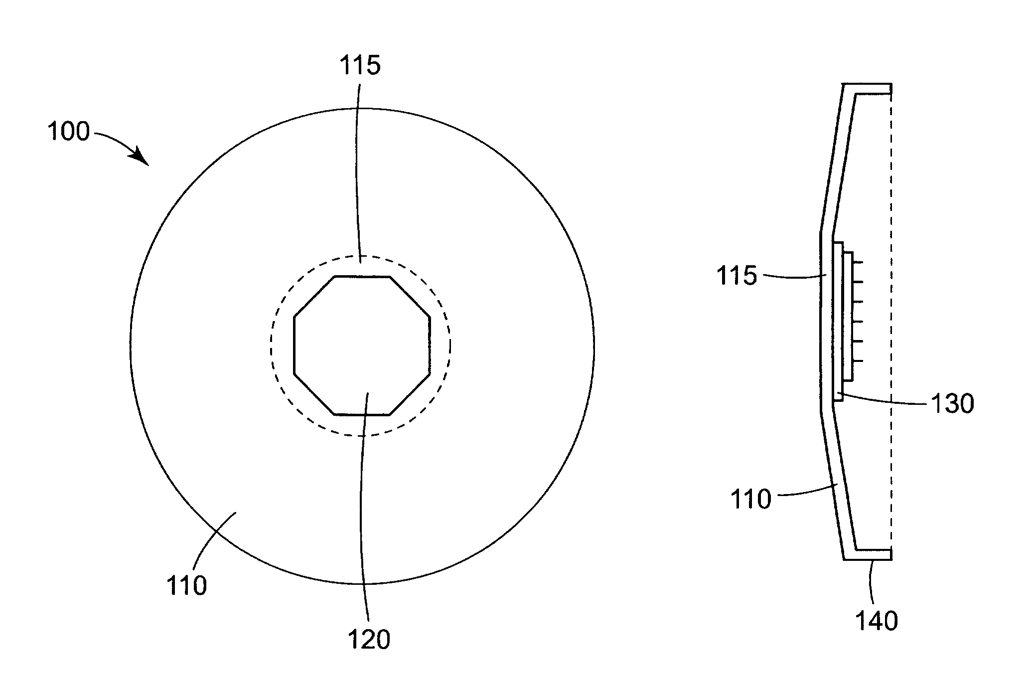
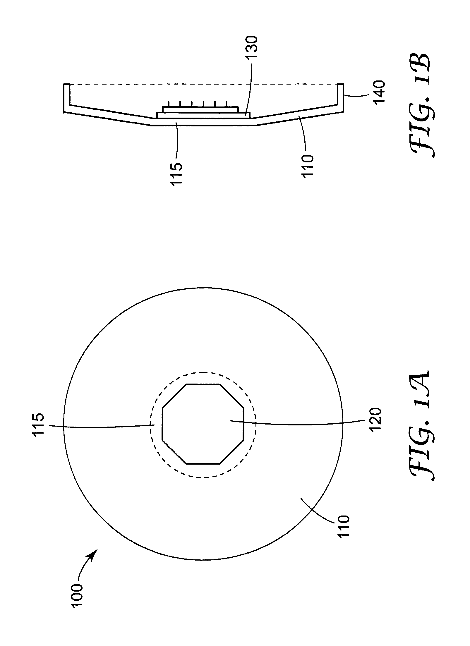
[0054]A device as generally shown in FIGS. 9A, B was tested to determine the velocity and displacement with which a microneedle device may be applied. The diameter of the flexible sheet member was approximately 4.5 cm. The diameter of the raised central area was approximately 1.8 cm. The spacer comprised 16 individual fins that were approximately 0.5 cm in height and 0.75 cm in width. The gap between each adjacent fin was approximately 1 mm. A small piece of a matte-finish reflective tape was applied to the underside of the raised central area for purposes of conducting the velocity / displacement measurement, however in practice a microneedle device would be attached to the underside of the raised central area. The flexible sheet member and spacer comprised steel with a thickness of approximately 0.3 mm. The device was placed against a fixture attached to a laser measuring device (Laser Vibrometer Controller model no. OFV-3001 and Laser Fiber Interferometer model no. OFV-502, Polytec...

example 2

[0055]The device of example 1 was tested according to the general mode of operation shown in FIGS. 7 and 8. That is, the raised central area was initially depressed and a small piece of a matte-finish reflective tape was applied to the side of the raised central area opposed to the spacer. The device was placed against a fixture attached to a laser measuring device (Laser Vibrometer Controller model no. OFV-3001 and Laser Fiber Interferometer model no. OFV-502, Polytec Inc., Tustin, Calif.) and aligned such that the laser could reflect off of the matte-finish reflective tape. The spacer was manually pushed in a direction parallel to the plane of the flexible sheet member (as shown in FIG. 8A) and the resulting velocity as a function of displacement of the raised central area is shown in FIG. 11. Total displacement was approximately 1.44 mm and the maximum velocity recorded was 7.06 m / s.


PUM


Abstract

An applicator (100) used to apply microneedle arrays (10) to a mammal. In particular, an application device for applying a microneedle device (120) to a skin surface comprising a flexible sheet (110) having a raised central area (115) attached to the microneedle device and a supporting member at or near the periphery of the flexible sheet, wherein the flexible sheet is configured such that it will undergo a stepwise motion in the direction orthogonal to the major plane of the sheet.

Description

CROSS REFERENCE TO RELATED APLICATIONS[0001]This application is a national stage filing under 35 U.S.C. 371 of PCT / US2005 / 041854 filed Nov. 18, 2005, which claims priority to 60 / 629,215, filed Nov. 18, 2004, the disclosure of which is incorporated by reference in its / their entirety herein.FIELD[0002]The present invention relates to applicators used to apply microneedle arrays to a mammal. The present method also relates to methods of applying a microneedle array or patch to a mammal.BACKGROUND[0003]Only a limited number of molecules with demonstrated therapeutic value can be transported through the skin, even with the use of approved chemical enhancers. The main barrier to transport of molecules through the skin is the stratum corneum (the outermost layer of the skin).[0004]Devices including arrays of relatively small structures, sometimes referred to as microneedles or micro-pins, have been disclosed for use in connection with the delivery of therapeutic agents and other substances...

Claims


Application Information

Patent Timeline
Patent Type & Authority Patents(United States)
IPC IPC(8): A61M5/00
CPCA61M37/0015A61M2037/0023A61M37/00
Inventor CANTOR, ADAM S.FREDERICKSON, FRANKLYN L.JOHNSON, PETER R.RINGSRED, TED K.
Owner KINDEVA DRUG DELIVERY LP
Why Eureka
Try Eureka