Display apparatus using pulsed light source

a technology of pulsed light and projection apparatus, which is applied in the field of system configuration and methods for controlling and operating projection apparatuses, can solve the problems of inability to provide a shorter pulse width than the lsb, affect image quality, and limit and difficulties, and achieve the effect of accurate modulated light intensity

Active Publication Date: 2012-09-18
OLYMPUS CORP +1
View PDF22 Cites 10 Cited by
  • Summary
  • Abstract
  • Description
  • Claims
  • Application Information

AI Technical Summary

Benefits of technology

[0014]A purpose of the present invention is to provide a technique capable of attaining an accurate intensity of modulated light without being influenced by the transition state between the ON and OFF states of the ON / OFF modulation of a mirror.
[0015]Another purpose of the present invention is to provide a technique capable controlling the intensity of modulated light independent of the speed of the tilt control of a mirror.
[0016]Yet another purpose of the present invention is to provide a technique capable of controlling a color temperature and a color balance without requiring an input video signal to be changed.
[0052]A thirty-sixth exemplary embodiment of the present invention provides the display apparatus according to the twentieth exemplary embodiment, wherein the component of a synthesized color within a displayed video image is increased by changing the respective cycles of the pulse emission of at least two colors, and thereby the brightness of the displayed video image is increased.
[0053]A thirty-seventh exemplary embodiment of the present invention provides the display apparatus according to the twentieth exemplary embodiment, wherein sequential emission of the light sources of a plurality of colors are multiple pulse emission of the light sources(s) having at least three colors, and adjusting the pulse width of the pulse emissions of the respective colors increases the white component within a displayed video image, thereby increasing the brightness thereof.

Problems solved by technology

Even though there have been significant advances made in recent years on the technologies of implementing electromechanical micro-mirror devices as spatial light modulator, there are still limitations and difficulties when these are employed to display high quality images.
Specifically, when the display images are digitally controlled, the image quality is adversely affected because the image is not displayed with a sufficient number of gray scales.
Due to the On-Off states implemented in the conventional systems, there is no way to provide a shorter pulse width than the LSB.
A limited gray scale leads to lower image quality.
However, these types of light sources perform poorly in high-speed switching that alternate between the ON and OFF states.
Thus, it is not possible to accurately control the light intensity in the transition state, between an ON state and an OFF state, for an ON / OFF modulation of a mirror.
This causes a degradation of image quality in the modulation control of a video image when using a spatial light modulator.
Increasing the oscillation speed of the mirror, however, is limited by a number of factors including the strength of a hinge constituting the mirror and the frequency of the control signal used for the tilt (i.e., oscillation) control, such as the ON / OFF control.
Thus, there will be a limitation in controlling light intensity when only the ON / OFF controls of the mirror are used to control the modulation of light intensities.
Because of this, further technical problems, such as an unnecessarily complex process circuit for the video, are introduced.

Method used


Image

  • Display apparatus using pulsed light source
  • Display apparatus using pulsed light source
  • Display apparatus using pulsed light source

Examples


embodiment 1

[0161]FIGS. 11 and 12 are timing diagrams for illustrating the operation sequences of a projection apparatus according to a preferred embodiment of the present invention.

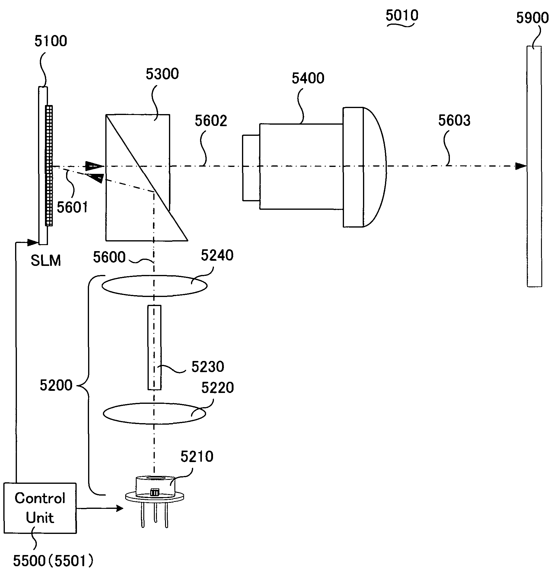
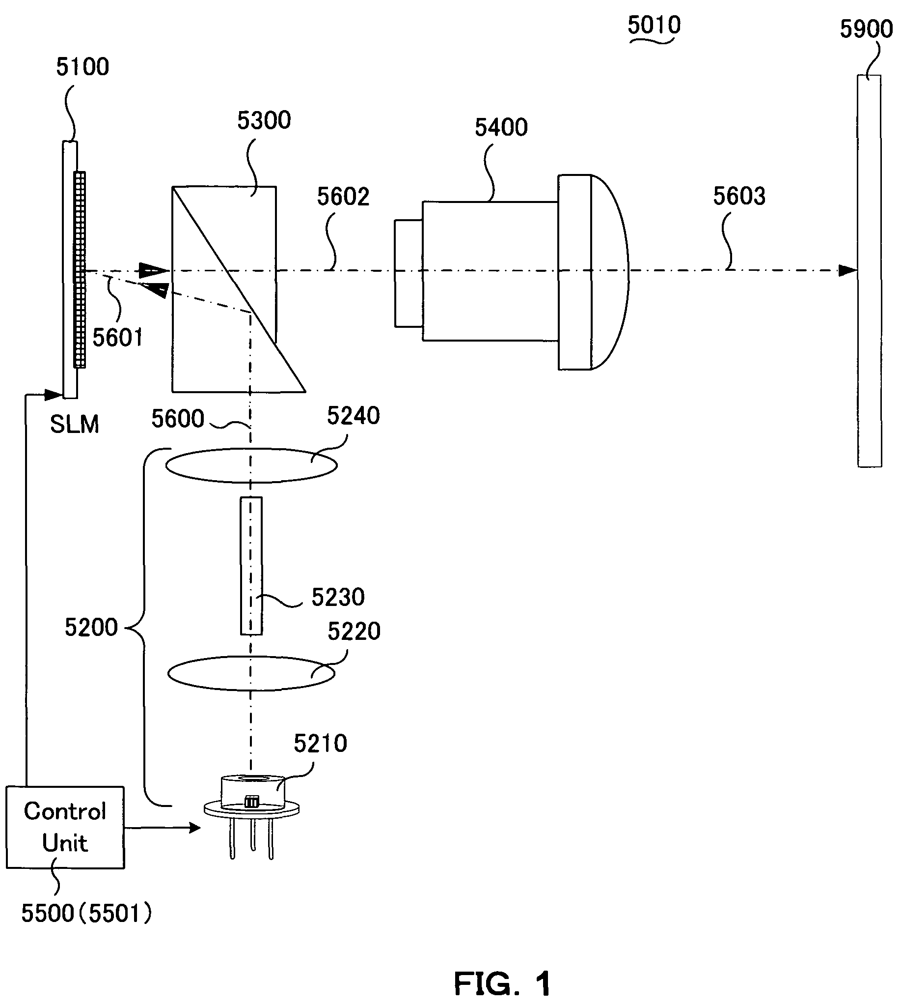
[0162]A projection apparatus according to the present embodiment may be implemented according the apparatuses described as a single-panel projection apparatus 5010, that includes the optical system as depicted in the above described FIG. 1 and the control system (i.e., the control 5500) as that depicted in the above described FIG. 3A. The image projection apparatuses carry out a projection display of a color image by implementing a color sequential display method.

[0163]Specifically, the SLM controller 5530 of the control unit 5500 as that implemented by the projection apparatus 5010 generates a light source profile control signal 5800 based on the input digital video data 5700. The light source profile control signals are then inputted to a light source control unit 5560 through a sequencer 5540A.

[0164]The light sou...


PUM


Abstract

The present invention provides a display apparatus, comprising: a light source; at least one spatial light modulator for modulating a luminous flux emitted from the light source; and a controller for processing inputted video image information and for controlling the light source and spatial light modulator, wherein the controller controls the light source and spatial light modulator so that the light source performs pulse emission for a period shorter than a period in which the spatial light modulator is controlled under a modulation state.

Description

CROSS REFERENCE TO RELATED APPLICATIONS[0001]This application is a Non-provisional application claiming a Priority date of Oct. 2, 2007 based on a previously filed Provisional Application 60 / 997,476 and a Non-provisional patent application Ser. No. 11 / 121,543 filed on May 4, 2005 issued into U.S. Pat. No. 7,268,932. The application Ser. No. 11 / 121,543 is a Continuation In Part (CIP) Application of three previously filed Applications. These three Applications are Ser. No. 10 / 698,620 filed on Nov. 1, 2003, Ser. No. 10 / 699,140 filed on Nov. 1, 2003 now issued into U.S. Pat. No. 6,862,127, and Ser. No. 10 / 699,143 filed on Nov. 1, 2003 now issued into U.S. Pat. No. 6,903,860 by the Applicant of this Patent Applications. The disclosures made in these Patent Applications are hereby incorporated by reference in this Patent Application.BACKGROUND OF THE INVENTION[0002]1. Field of the Invention[0003]The present invention relates generally to the system configuration and methods for controllin...

Claims


Application Information

Patent Timeline
Patent Type & Authority Patents(United States)
IPC IPC(8): G02B26/00
CPCG02B26/0833G02B27/1026G02B27/1033G09G3/2077G09G3/346G09G3/3406G09G2310/0237G09G2320/0633G09G2320/064G09G2320/0646G09G2320/0653
Inventor ENDO, TAROARAI, KAZUMAMAEDA, YOSHIHIROISHIL, FUSAO
Owner OLYMPUS CORP
Why Eureka
Try Eureka