Method for recovering a bit stream from a radio signal

a radio signal and bit stream technology, applied in diversity/multi-antenna systems, amplitude demodulation, site diversity, etc., can solve the problems of inability to scale, and inability to meet the requirements of a highly expensive backplane, so as to avoid the different handling of soft and soft handover, avoid softer handover performance, and achieve negligible performance loss

Active Publication Date: 2012-09-18
ALCATEL LUCENT SAS
View PDF2 Cites 5 Cited by
  • Summary
  • Abstract
  • Description
  • Claims
  • Application Information

AI Technical Summary

Benefits of technology

[0015]Examples of embodiments of the invention advantageously provide: a method, a receiving station, a base station router, as well as a network, all of which allowing for recovering a bit stream with high quality from a radio signal by combining at least two received radio signals while keeping the transport capacity required for the combining of the radio signals at a comparatively low level.
[0017]Therefore, by making use of the invention, it is possible to profit from softer handover in every case, whether a mobile station is served by several receiving stations of one base station or by receiving stations of different base stations, without running into problems of huge data transport requirements. The architecture of the corresponding network becomes more flat, the different handling of soft and softer handover is avoided, as all the links are “softer”.
[0018]Consequently, the transport capacity required for the scheme proposed above lies in-between the two extremes of transport capacity defined by the soft and softer handover schemes: Considering the example of a 384 kbit / s service for the mobile user, soft handover implies a data transport at 384 kbit / s, whereas softer handover implies 76 Mbit / s. Compared to the transport capacity required for the softer handover, the newly invented scheme requires a medium transport capacity but offers nearly identical softer handover performance as compared to the extreme case of 76 Mbit / s. Thus, compared to today's case of softer handover at borders between different receiving stations of the same base station by MRC combining of IQ baseband data, a negligible performance loss is faced; compared to today's soft handover between base stations, a significant performance gain is obtained.
[0021]In a highly preferred variant, in each receiving station, symbols contained in the demodulated data stream are scaled to a normalized symbol space, preferably in a blockwise manner, the data streams with the scaled symbols being quantized and transferred to the first receiving station together with a signal indicative of the noise variance of the scaled symbols. In this case, the symbols, e.g. of the 16-QAM modulation scheme, are transferred between the receiving stations in a normalized symbol space by pre-scaling the in-phase and quadrature signal components and by pre-computing the offset for a given block of data. These quantities may be re-calculated at pre-defined intervals (e.g. after each block of data), as described in the paper cited above. The normalized (complex) symbols may then be added up in the first receiving station directly to form a combined symbol stream, taking the noise variance which is indicative of the reliability of the transferred symbols into account. The LLRs may then be computed afterwards from the single combined symbol stream. As an alternative, the noise variance which is transferred together with each demodulated data stream may be used to first calculate the LLRs of each of the data streams within the first receiving station, the data streams of log-likelihood ratios of different data streams being added up afterwards in the way described above. Of course, it is also possible to transfer the symbols without blockwise scaling, the scaling being performed in the first receiving station in this case. However, the scaling further reduces the amount of data that has to be exchanged via the backhaul network.
[0028]In a preferred embodiment, the transfer device is designed to transfer a signal indicative of the noise variance of the scaled symbols from the at least one further receiving station to the first receiving station. The signal indicative of the noise variance of the scaled symbols is indicative of the reliability of the symbols, and is used for combining the symbols in the standard symbol space directly by weighting the symbols of different data streams according to their noise variance, thus further improving the quality of the recovered bit stream.

Problems solved by technology

This is especially problematic if the receiving stations S1 to S3 and their respective RF heads RF1 to RF3 are installed remotely and the CPRI data has to be transported over larger distances in the context of a so-called base station hotel concept.
The concept described above is furthermore not easily scalable if more and more receiving stations are to be added with upgrades, as the switch fabric has to be adapted in this case.
Considering the six antenna paths arising from three receiving stations plus receiving diversity this implies a total bandwidth of 76.8×6=460.1 Mbit / s, requiring an extremely costly backplane.
It would be desirable to have also softer handover combining between different base stations, but due to enormous bandwidth requirements in the backhaul, this is not feasible.
It would also imply that the concentrator function, which today is a simple frame selection task, would become very computationally intense, especially in light that a radio network controller RNC has to handle a few hundred base stations.

Method used


Image

  • Method for recovering a bit stream from a radio signal
  • Method for recovering a bit stream from a radio signal
  • Method for recovering a bit stream from a radio signal

Examples


Embodiment Construction

[0037]Throughout the following description, like elements shown the drawings will be referred to with like reference numerals.

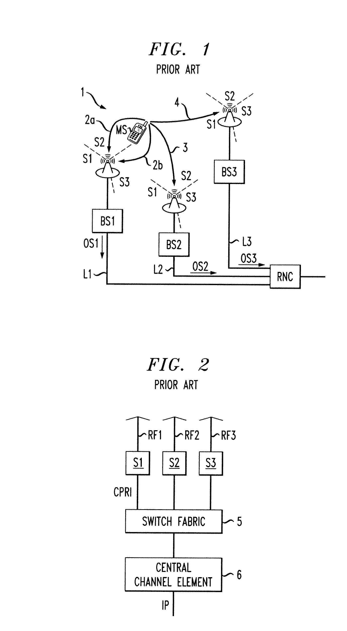
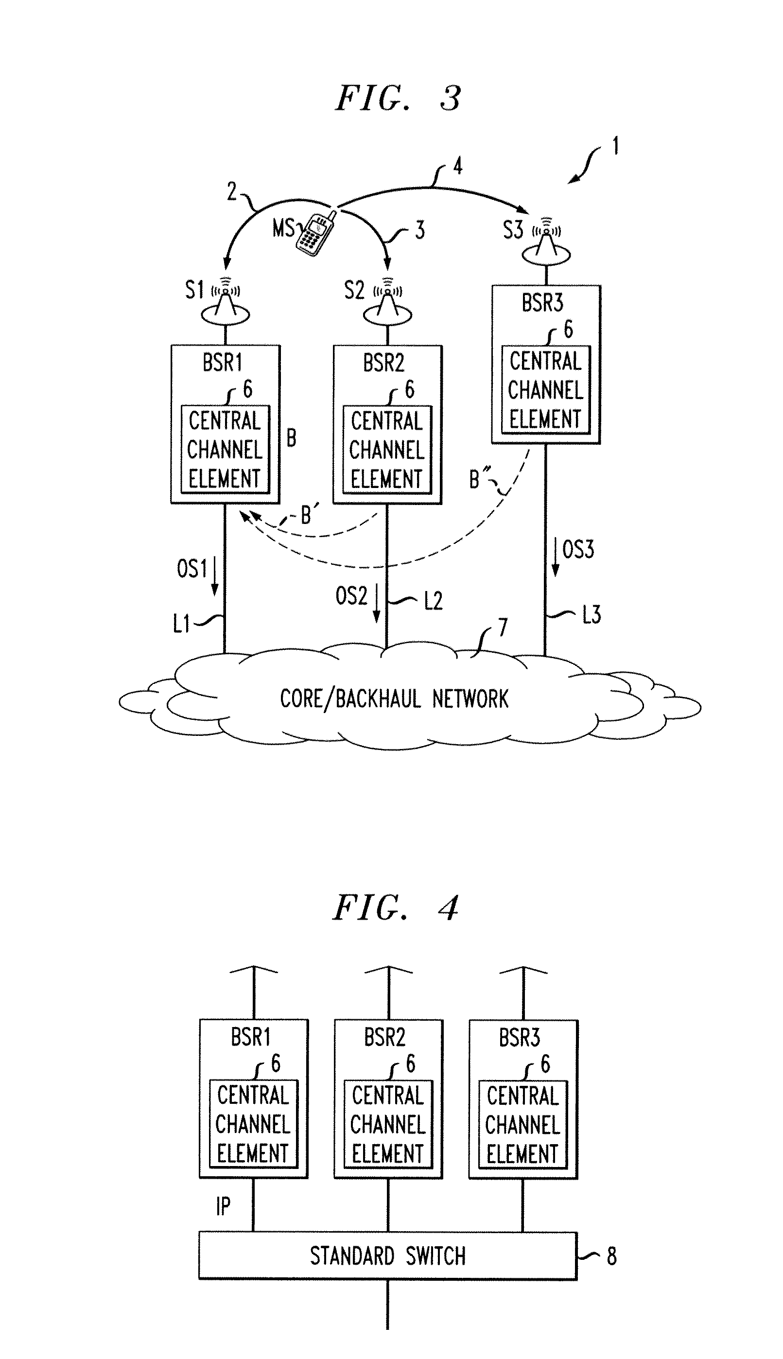
[0038]FIG. 3 shows a network 1 which differs from the network 1 shown in FIG. 1 in that it is a non-hierarchical network, the base stations BS1 to BS3 of FIG. 1 being replaced by base station routers BSR1 to BSR3, each being connected via a respective link L1 to L3 to the internet which serves as a transfer device in form of a core / backhaul network 7 within the wireless network 1. More precisely, as is also shown in FIG. 4, each of the three base station routers BSR1 to BSR3 comprises its own channel element 6 and thus produces an output signal OS1 to OS3 of standard IP data which is provided to a standard switch 8 located in the core network 7. The base station routers BSR1 to BSR3 each comprise only a single receiving station S1 to S3 which is connected to a mobile station MS located in the coverage area of each of the three base station routers BSR1 to BSR...


PUM


Abstract

The invention relates to a method for recovering a bit stream from a radio signal (2, 3, 4) received in a first receiving station (S1) and at least one further receiving station (S2, S3), the method comprising the steps of: in each of the receiving stations (S1 to S3), demodulating the received radio signal (2, 3, 4) to form a demodulated data stream (B, B′, B″), transferring the at least one demodulated data stream (B′, B″) from the at least one further receiving station (S2, S3) to the first receiving station (S1), in the first receiving station (S1), generating a combined data stream from the demodulated data streams (B, B′, B″) of each of the receiving stations (S1 to S3), and performing a hard decision on the combined data stream for recovering the bit stream.

Description

BACKGROUND OF THE INVENTION[0001]The invention relates to a method for recovering a bit stream from a radio signal received in a first receiving station and in at least one further receiving station, to a receiving station for recovering a bit stream from a radio signal received in the receiving station and at least one further receiving station, to a base station router comprising at least one such receiving station and a channel element, and to a network for recovering a bit stream from a radio signal.[0002]When a radio signal emitted by a mobile station is received in two or more different receiving stations, it is possible to combine the received signals in such a way that the bit stream which has been emitted by the mobile station can be recovered with a higher quality as compared to the case that the reconstruction is performed based on a single received signal. For recovering such a bit stream by combining two or more received signals, two schemes known as softer handover and...

Claims


Application Information

Patent Timeline
Patent Type & Authority Patents(United States)
IPC IPC(8): H04L27/06
CPCH04L69/04H04B7/022
Inventor FISCHER, GEORGOBERNOSTERER, FRANK GERHARD ERNSTGUNREBEN, PETER CHRISTIAN
Owner ALCATEL LUCENT SAS
Why Eureka
Try Eureka