Multiple diverging projectile system

a projectile system and multi-division technology, applied in the direction of projectiles, weapons, ammunition, etc., can solve the problems of premature ignition of the explosive charge within the projectile, premature structural failure, and relatively high pressure to fully eliminate the combustion residu

Inactive Publication Date: 2012-09-25
BAE SYST INFORMATION & ELECTRONICS SYST INTERGRATION INC
View PDF14 Cites 1 Cited by
  • Summary
  • Abstract
  • Description
  • Claims
  • Application Information

AI Technical Summary

Benefits of technology

[0007]The above-described problems are addressed and technical solutions are achieved in the art by a system and components thereof for efficiently firing multiple projectiles in a parallel or a diverging manner, according to various embodiments of the present invention. Some of these embodiments allow the multiple projectiles to be fired repeatedly and without the use of curved barrels.
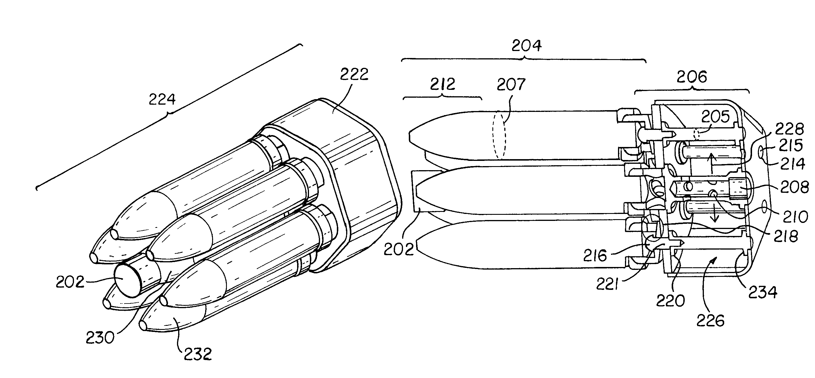
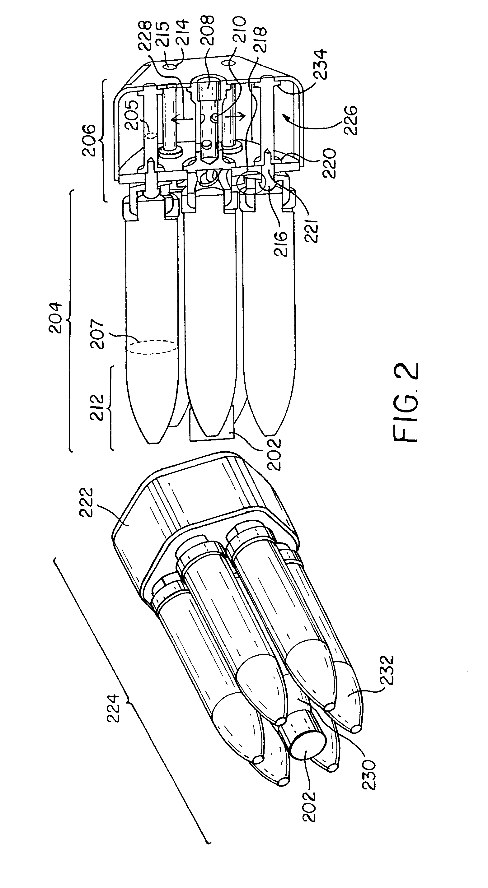
[0011]In some embodiments, the tail-end portion can include openings to distribute energy from an ignition charge. According to this configuration, the tail-end portion, or a portion thereof, can be inserted into an alignment casing of a cartridge that contains a first combustible charge, and combustion energy of the ignition charge can be uniformly distributed to the first combustible charge through the tail-end portion, thereby causing an efficient firing of the cartridge.
[0013]In some embodiments, the tail-end portion includes a ball joint upon which the body portion of the projectile moves or rotates causing an angle between the body portion and the tail-end portion. In some embodiments, a space exists in the body portion of the projectile adjacent to the ball joint into which the ball joint translates when the angle between the body portion and the tail-end portion is caused. In some of these embodiments, the body portion is centered on the ball joint when there is no angle between the body portion and the tail-end portion, and, when the ball joint is in the space, the body portion is off-center with respect to the ball joint. In embodiments that include the ball joint, the ball joint can be physically captured by the body portion such that the body portion and tail-end portion remain connected when the angle between the body portion and the tail-end portion is caused. Embodiments that include the ball joint allow a projectile initially oriented parallel to the cartridge axis to reorient as necessary to other features of the gun system.
[0015]In some embodiments of the present invention, a projectile cartridge includes a plurality of projectiles and an alignment casing. The plurality of projectiles each include (a) any embodiment of the body portion described herein and (b) any embodiment of the tail-end portion described herein. The alignment casing encloses a portion of each of the plurality of projectiles and includes a first combustible material or charge. In some embodiments, the ball joint is a portion of the tail-end portion of a projectile that remains outside of (i.e. is not enclosed by) the alignment casing, so that any combustible material in the alignment casing is not disturbed or prematurely ignited by movement on the ball joint. The alignment casing contains features that assist in aligning the plurality of projectiles for ejection in a parallel or diverging manner. In some embodiments, the alignment casing arranges the plurality of projectiles to have a center projectile surrounded by peripheral projectiles.
[0018]In an embodiment of the present invention, a projectile system includes a barrel system and a projectile cartridge. The barrel system includes multiple barrels extending in a diverging manner. The projectile cartridge includes an alignment casing and a plurality of projectiles. The alignment casing encloses a portion of each of the plurality of projectiles, includes a first combustible material or charge, and is made of a second combustible material. The alignment casing gains additional structural support from the tail-end portions of the plurality of projectiles. The alignment casing arranges the plurality of projectiles to have a center projectile surrounded by peripheral projectiles. The alignment casing contains features that assist in respectively aligning the plurality of projectiles with the barrels of the barrel system when the plurality of projectiles are inserted into the barrels of the barrel system. The plurality of projectiles each include a body portion and a tail-end portion connected to the body portion. The tail-end portion of the center projectile includes openings that distribute energy passing through the tail-end portion from combustion of an ignition charge contained within the tail-end portion of the center projectile. The distributed energy causes combustion of the first and second combustible material and causes the plurality of projectiles to eject from the barrel system. The tail-end portion of a peripheral projectile includes a ball joint and a space adjacent to the ball joint causing an angle and a translation between the corresponding body portion and the corresponding tail-end portion, allowing the peripheral projectile to fit into its respective barrel of the barrel system and eject therefrom in a diverging manner. As such, a relatively weak alignment casing supported by tail-end portions of projectiles can be used to launch multiple projectiles in a diverging manner while entirely evacuating the chamber and eliminating unnecessary stresses on the projectiles. Further, as discussed above, the ball joint can be a portion of the tail-end portion of the peripheral projectile that is not enclosed by the alignment casing. Such an arrangement can, in some configurations, help prevent premature combustion or other disturbance of any combustible material inside or comprising the alignment casing during actuation of the ball joint.

Problems solved by technology

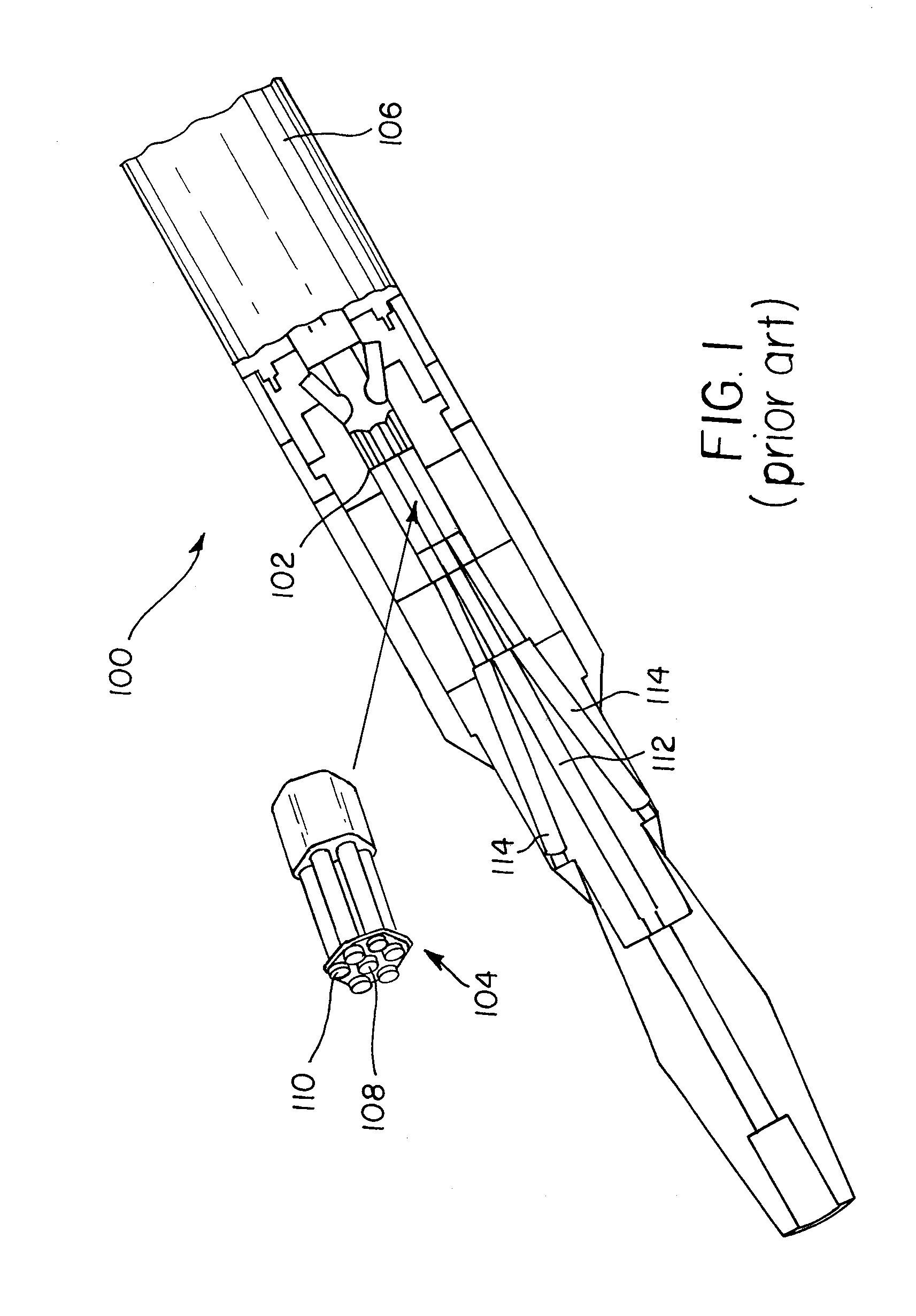
As such, these designs, when chambered, require relatively high pressures to fully eliminate combustion residue.
While there is some precedent for using curved barrels 114 to achieve a diverging projectile pattern, this methodology forces peripheral projectiles 110 to undergo a high G-load turn during launch which induces high stresses on the bodies of the peripheral projectiles that could lead to premature structural failure or premature ignition of the explosive charge within the projectile should it exist.

Method used


Image

  • Multiple diverging projectile system
  • Multiple diverging projectile system
  • Multiple diverging projectile system

Examples


Embodiment Construction

[0026]The invention is inclusive of combinations of the embodiments described herein.

[0027]References to a particular embodiment do not necessarily refer to the same embodiment or embodiments, and particular embodiments are not mutually exclusive, unless so indicated or as are readily apparent to one of skill in the art. The use of singular or plural in referring to an embodiment or embodiments and the like is not limiting. Further, it should be noted that, unless otherwise explicitly noted or required by context, the word “or” is used in this disclosure in a non-exclusive sense.

[0028]FIG. 3 illustrates a multiple diverging projectile system 300, according to an embodiment of the present invention. The projectile system 300 includes a barrel system 302 and a projectile cartridge 224. The barrel system 302 includes a chamber 308 into which the projectile cartridge 224 is inserted. The barrel system 302 also includes multiple barrels 304, 306 that extend linearly in a diverging manner...


PUM


Abstract

A system for firing multiple projectiles in a parallel or diverging manner is provided. The system can comprise tail-end portions of projectiles that add structure to a cartridge, provide for efficient combustion, allow projectiles to transition from a straight configuration in the cartridge to a splayed configuration in a chamber, and ensure complete evacuation of the chamber. The system can include a tail-end portion of a particular projectile with openings that distribute energy from combustion of an ignition charge, facilitating firing of multiple projectiles. A tail-end portion of a projectile can include a ball joint upon which the body portion of the projectile moves causing an angle between the body portion and the tail-end portion. A space can exist in the body portion adjacent to the ball joint to allow off-center shifting of the body portion with respect to the ball joint.

Description

STATEMENT OF GOVERNMENT INTEREST[0001]The invention was made with United States Government support under Contract No. W15QKN-04-C-1110 awarded by the Army Research and Development Command (ARDEC). The United States Government has certain rights in this invention.FIELD OF THE INVENTION[0002]This invention relates to a system and components thereof for firing multiple projectiles in a parallel or diverging manner.BACKGROUND OF THE INVENTION[0003]FIG. 1 illustrates a conventional drilling gun 100 configured to be inserted into a shaft in which drilling is to occur. The drilling gun 100 includes a chamber 102 into which a cartridge 104 from a magazine 106 is inserted. The cartridge 104 includes a center projectile 108 surrounded by six peripheral projectiles 110. All of the projectiles 108, 110 are parallel to each other when inserted into the chamber. The center projectile 108 fits into a center barrel 112 of the gun 100. The peripheral projectiles 110 respectively fit into the periphe...

Claims


Application Information

Patent Timeline
Patent Type & Authority Patents(United States)
IPC IPC(8): F42B10/06
CPCF41F1/08F42B10/40F42B10/60
Inventor MACHINA, MARK H.RALEIGH, MICHAELMOUNT, KRISTOPHER P.MITCHELL, KENNETH W.BOHNET, MICHAEL A.
Owner BAE SYST INFORMATION & ELECTRONICS SYST INTERGRATION INC
Why Eureka
Try Eureka