Steam power plant

a steam power plant and steam technology, applied in steam engine plants, indirect carbon dioxide mitigation, machines/engines, etc., can solve the problems of limited steam temperature, thermal transfer of hot gas to the medium to be heated, and limited steam temperature permissible, so as to achieve fast output regulation and high steam temperature

Inactive Publication Date: 2006-11-30
SIEMENS AG
View PDF5 Cites 2 Cited by
  • Summary
  • Abstract
  • Description
  • Claims
  • Application Information

AI Technical Summary

Benefits of technology

[0026] The internal additional firing implemented by means of the combustion chamber of a claimed steam power plant can be made available very quickly during operation of the steam turbine. It only requires ignition of the fuel introduced into the combustion chamber; the time required in particular to heat up known heat exchanger surfaces in particular is not required.
[0027] A claimed steam power plant also has the advantage that combustion products and / or waste gas do not necessarily have to be removed from the combustion chamber by means of a separate discharge facility, as they are carried along with the flow of steam and can be extracted at another point in the steam circuit, for example the said condenser. Also a higher steam temperature can be achieved with the invention, without having to change the design of the steam generator.
[0028] A claimed steam power plant can in particular also be used to supply energy in peak load periods or to boost the system frequency of an electrical energy supply network; a claimed steam power plant allows fast output regulation and can be used in a very flexible manner.

Problems solved by technology

Since with the heat exchangers known from the prior art, which are used in steam generators of known steam power facilities, the energy from a hot gas is transferred to the medium to be heated by means of a material of the heat exchanger surface heated by the hot gas, the quantity of energy that can be transferred to the medium to be heated, for example water and / or steam, is limited by the material characteristics of the heat exchanger surface.
With known steam power facilities the permissible steam temperatures are therefore limited, since the heat exchanger surface transferring the thermal energy cannot be heated up to an arbitrary high temperature due to its material characteristics and the thermal load limits associated therewith.
The thermal transfer of hot gas to the medium to be heated is also subject to a delay, essentially due to the time required to heat up the heat exchanger surface.

Method used


Image

  • Steam power plant
  • Steam power plant

Examples


Embodiment Construction

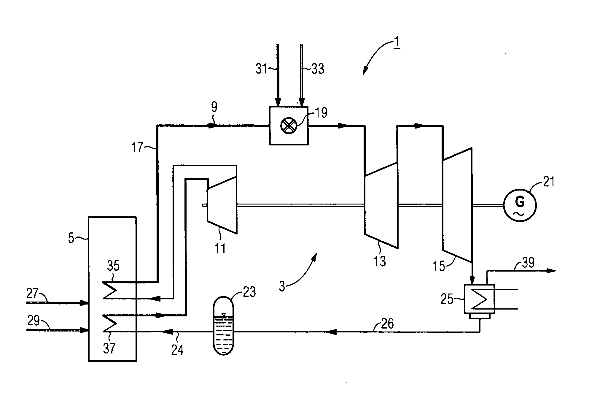
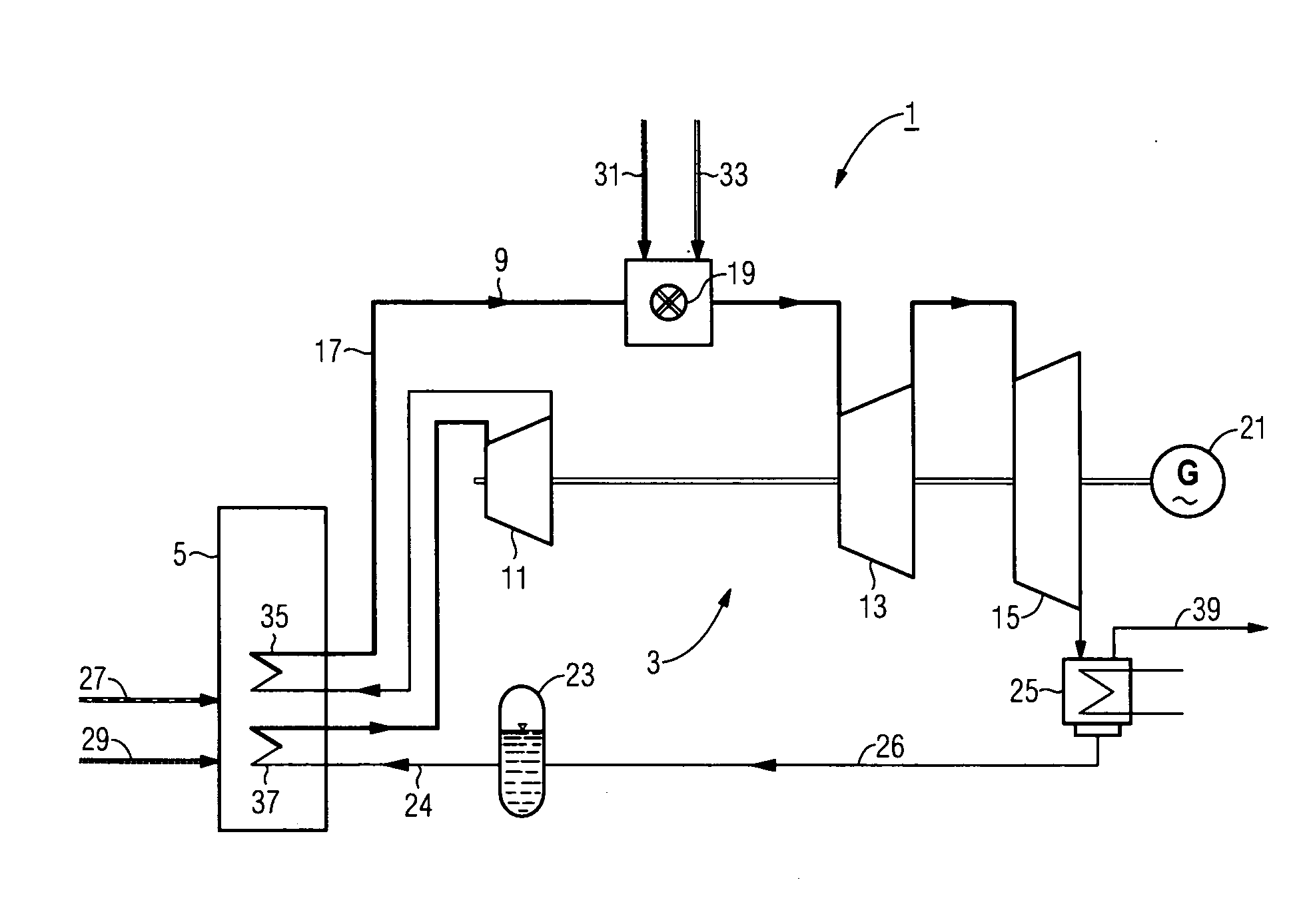
[0031] The FIGURE shows a claimed steam power plant 1, having a steam turbine 3 coupled to a generator 21 and a fired steam generator 5.

[0032] The steam turbine 3 has three stages, a first turbine stage 11, a second turbine stage 13 and a third turbine stage 15, which are configured as a high-pressure stage, a medium-pressure stage and a low-pressure stage.

[0033] In the present exemplary embodiment in the FIGURE the steam generator 5 is a boiler fired by coal 27, to which combustion air 29 is supplied to maintain the coal-firing process.

[0034] A heating surface 37 is disposed in the area of the hot end of the steam generator 5 and an intermediate superheating heating surface 35 is disposed in a lower temperature area.

[0035] The heating surface 37 serves to heat a water supply 24 from a water supply tank 23 in the steam generator 5 such that operating steam can be supplied to the first turbine stage 11.

[0036] After partial expansion in the first turbine stage 1 the steam is subj...


PUM


Abstract

An inventive steam power plant comprises at least one steam turbine and a steam generator, whereby a combustion chamber, in the direction of the flow of steam, is mounted after a first turbine stage and before a second turbine stage of the steam turbine, and the flow of steam inside a combustion chamber can be heated by mixing it with a hot gas that can be produced inside said combustion chamber.

Description

CROSS REFERENCE TO RELATED APPLICATION [0001] This application is the US National Stage of International Application No. PCT / EP2004 / 008348, filed Jul. 26, 2004 and claims the benefit thereof. The International Application claims the benefits of German Patent application No. 20313279.3 DE filed Aug. 27, 2003, both of the applications are incorporated by reference herein in their entirety.FIELD OF THE INVENTION [0002] The invention relates to a steam power plant with at least one steam turbine and a fired steam generator. BACKGROUND OF THE INVENTION [0003] With known steam power plants operating steam for a steam turbine is generally generated in a fired steam generator, with the energy contained in a hot gas being transferred to one or more heat exchangers, which are supplied with water, such that operating steam can be generated by heating this water, or which are supplied with steam such that superheating of the steam can be achieved by means of a last-mentioned heat exchanger; suc...

Claims


Application Information

Patent Timeline
Patent Type & Authority Applications(United States)
IPC IPC(8): F01K13/00F01K7/16F01K21/04F01K25/00
CPCF01K25/005F01K21/04F01K7/00F01K21/00F01K7/06Y02E20/34
Inventor HABERBERGER, GEORGKAIL, CHRISTOPH
Owner SIEMENS AG
Why Eureka
Try Eureka