Expandable raku kiln

a raku kiln and expandable technology, applied in the field of expandable raku kilns, can solve the problems of limiting the height of the firing chamber, the size of the closed kiln, and the difficulty of large raku pieces, so as to facilitate the longer and larger pieces, the effect of more efficient firing and more efficient pottery

Active Publication Date: 2016-06-07
JOHNSON KELLOGG S
View PDF13 Cites 0 Cited by
  • Summary
  • Abstract
  • Description
  • Claims
  • Application Information

AI Technical Summary

Benefits of technology

[0007]There is thus advantageously provided a firing chamber is provided that is placed above a burner chamber having two venturi burners that are centered under the kiln floor and spaced apart equally from the center of the kiln floor. The burners heat an area under a kiln shelf that is below the kiln floor to create a superheated volume bounded by the kiln floor, the kiln shelf and an encircling fire ring. The superheated volume of gas causes the kiln floor and shelf to heat rapidly and radiate thermal energy to fire the pottery and heat the chamber walls, while the shelf and fire ring deflect the flame to the firing chamber where the chamber walls quickly heat and radiate thermal energy to the pieces being fired. The radiant heating, especially by the kiln floor and shelf, is believed to be more efficient than convection heating at the kiln operating temperatures, thereby providing for more efficient firing of the pottery.
[0008]The kiln floor is enclosed in a firing chamber that is configured to be extendable in height. For normal sized pottery pieces the standard chamber can be used which is about two feet high. If larger pieces are to be fired a cylindrical extension can be fastened to the upper portion of the base chamber to double the height to about four feet. Further extensions are possible thereby readily accommodating longer and larger pieces of pottery while allowing adjustment of the chamber size for more efficient operation.
[0009]The chamber is removable from the fire ring and is moved along a vertical axis by a post and pulley system that uses a guide post to maintain vertical movement of the chamber while the chamber walls are around the working volume of the chamber. But once the chamber bottom has cleared the working volume the guide post no longer maintains the chamber position and the post rotates about its longitudinal axis to move the chamber off to the side, thus removing the chamber from above the kiln floor to enable easy and fast access to the kiln floor without hindrance by a chamber immediately above the fired pieces. The pulley system may be manually operated for simplicity, or electrically operated for easier and faster positioning of the firing chamber. A tubular sleeve fastened to the outside of the chamber and sliding over a post slightly higher than the chamber provides a simple guide post, and if located by or on the lifting post it also reduces blockage of access to the kiln floor.

Problems solved by technology

But for larger pieces of pottery such closed kilns are too small.
Further, some types of pottery firing, such as raku, use combustion products and smoke to achieve the desired finish, but the combustion products may coat the oven walls and adversely affect the firing of later pieces of pottery so closed, oven type kilns present problems for large pieces of raku pottery.
That in turn requires a very tall space within which to place the kiln and limits the height of the firing chamber.
Further, the three vertical frames impede access to the kiln both during firing and during loading and unloading of pottery into the kiln.
Moreover, when the chamber is lifted it is very hot and having it suspended above the fired pottery makes it hazardous for users to access the fired pottery without touching the hot chamber.
That provides an updraft heater, but wastes a lot of heat as not only does heated gas rise, but the burners are effectively orientated so as to blow the hot gas outward and upward, where it vents through openings at the top of the kiln.

Method used


Image

  • Expandable raku kiln
  • Expandable raku kiln
  • Expandable raku kiln

Examples


Embodiment Construction

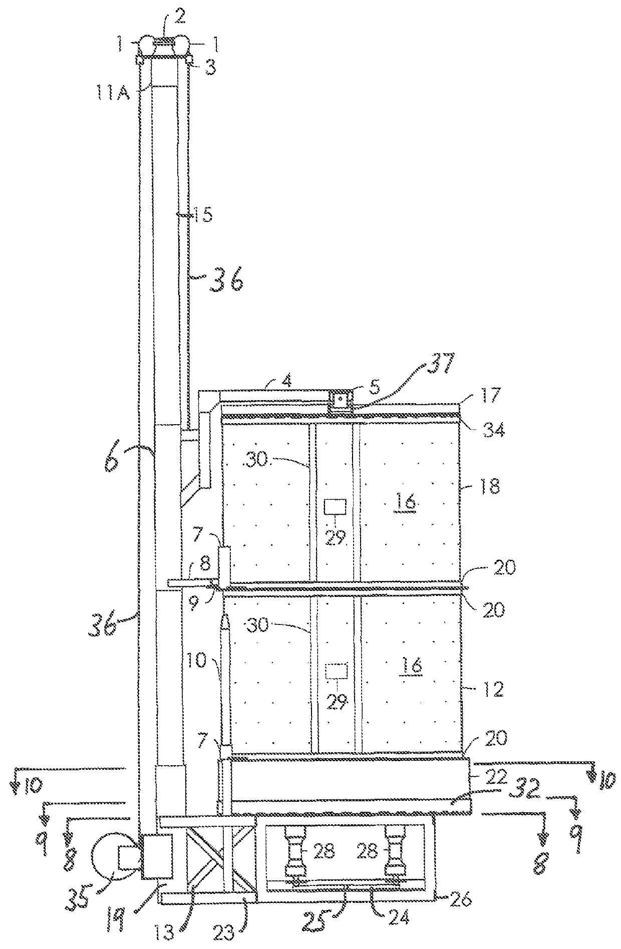
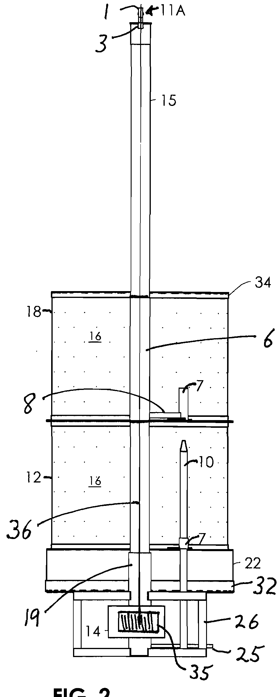
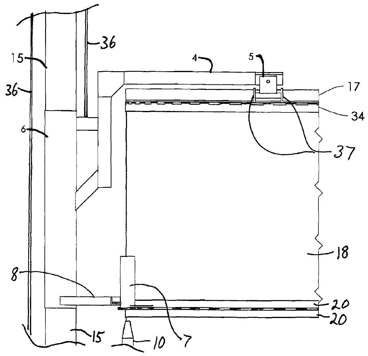
[0026]The improved kiln is described with reference to FIGS. 1 and 2 and 8, going from the bottom up, where the relative terms up, down, above, below, upward and down ward are relative the direction of gravity on the kiln assembly as show in FIGS. 1 and 2. Further, as used herein the relative directions inner and outer are with reference to the longitudinal axis of the kiln during heating, with inner referring to a direction toward that longitudinal axis an outer being the opposite direction.

[0027]The kiln has a support frame 26 that rests on the floor and provides a space to orientate venturi burners 28 fed by gas inlet 25 (FIG. 8) that is in fluid communication with manifold 24 (FIG. 8). The frame 26 is shown as an open, box framework with the burners 28 vertically oriented inside the frame 26 and spaced apart an equal distance from a longitudinal axis of the kiln which axis may pass through a center of the frame 26. The burners 28 and manifold 24 may be fastened to the frame 26 i...


PUM


Abstract

A raku kiln has a fire ring with a cylindrical sidewall and bottom made of refractory material with a kiln shelf supported a few inches above the bottom to enclose a space that is superheated by burners. A firing-chamber rests on the fire ring and is lifted by a two aligned pulleys on top of a pole which rotates to move the chamber out of the way. A vertical pole mates with tubes on the chamber for vertical guidance during raising and lowering of the chamber. Flanges on the lower end of the chamber allow adding an extension chamber.

Description

CROSS-REFERENCE TO RELATED APPLICATIONS[0001]The application claims the benefit under 35 U.S.C. §119e to provisional patent application No. 61 / 750,310 filed Jan. 8, 2013, the entire contents of which are incorporated herein by reference.STATEMENT RE: FEDERALLY SPONSORED RESEARCH / DEVELOPMENT[0002]Not applicableBACKGROUND[0003]Pottery kilns require high temperatures to fire the pottery, with the temperature varying with the type of clay used, any glaze finish applied to the clay and other factors. In order to conserve fuel needed to maintain the high temperatures for firing, most kilns used insulated overs. But for larger pieces of pottery such closed kilns are too small. Further, some types of pottery firing, such as raku, use combustion products and smoke to achieve the desired finish, but the combustion products may coat the oven walls and adversely affect the firing of later pieces of pottery so closed, oven type kilns present problems for large pieces of raku pottery.[0004]For la...

Claims


Application Information

Patent Timeline
Patent Type & Authority Patents(United States)
IPC IPC(8): F27B5/02F27B17/00F27D1/18
CPCF27B17/0041F27D1/1808
Inventor JOHNSON, KELLOGG S.
Owner JOHNSON KELLOGG S
Why Eureka
Try Eureka