Electromagnetic actuator

a technology of electromagnets and actuators, applied in the direction of electromagnets, valve details, cores/yokes, etc., can solve the problems of long valve transition time, inability to achieve the speed of actuation according to the prior art, and inability to accurately commutate the effect of speed

Active Publication Date: 2012-09-25
ARTEMIS INTELLIGENT POWER
View PDF13 Cites 11 Cited by
  • Summary
  • Abstract
  • Description
  • Claims
  • Application Information

AI Technical Summary

Benefits of technology

[0008]The present invention solves the aforementioned problems and allows a solenoid valve that is fast enough for accurate commutation of a reciprocating fluid volume at the speed of a diesel engine. In addition it has wider application wherever valves need to be actuated quickly, or indeed as a fast direct solenoid actuator outside of the domain of fluid valves.

Problems solved by technology

Solenoid valves according to the prior art cannot achieve this speed of actuation.
These effects cause a long valve transition time.
Because the period during which the armature is in motion is long, and the latency of the coil is long, there is much uncertainty about the exact time when the valve reaches its actuated position.

Method used


Image

  • Electromagnetic actuator
  • Electromagnetic actuator
  • Electromagnetic actuator

Examples


Embodiment Construction

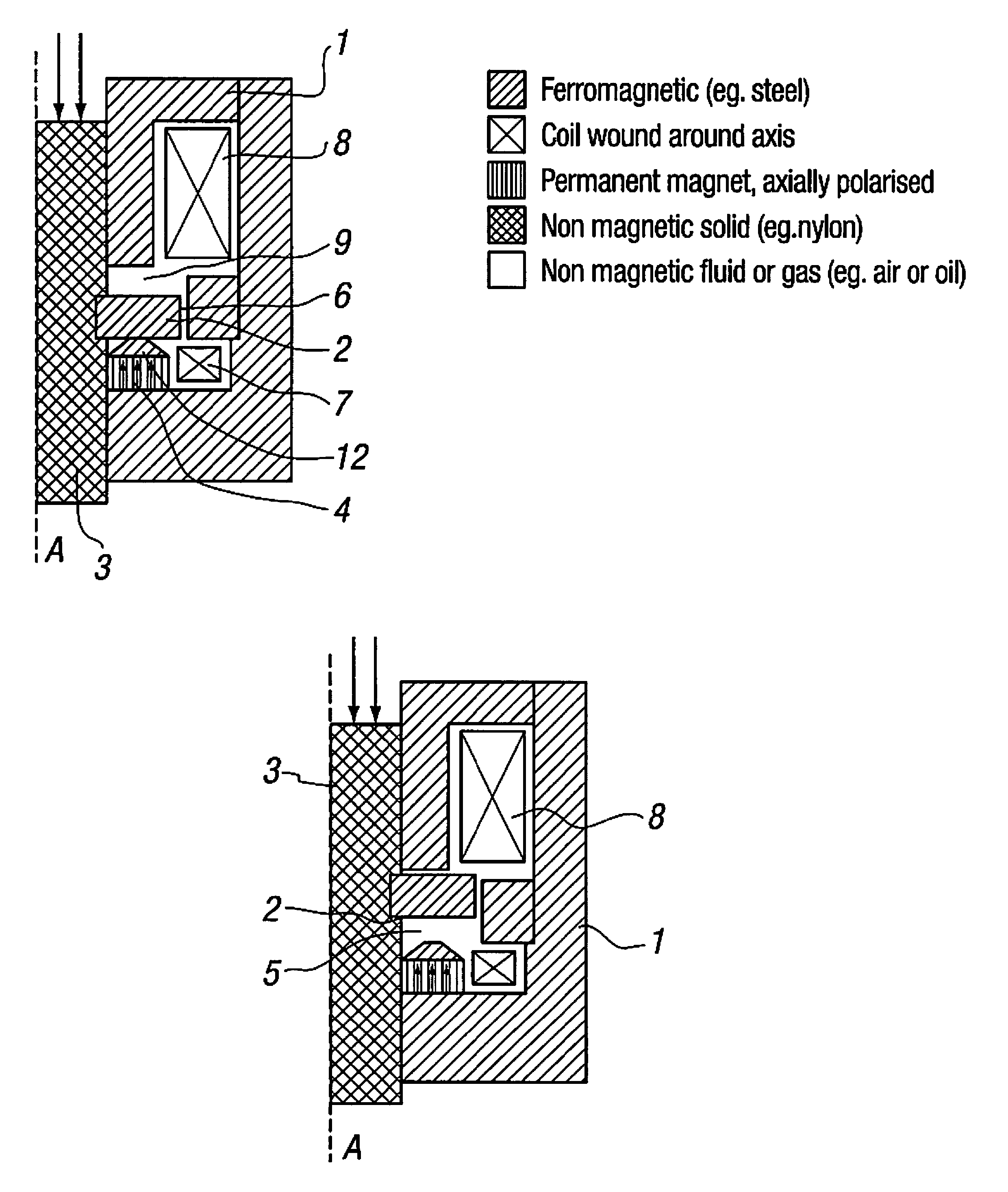
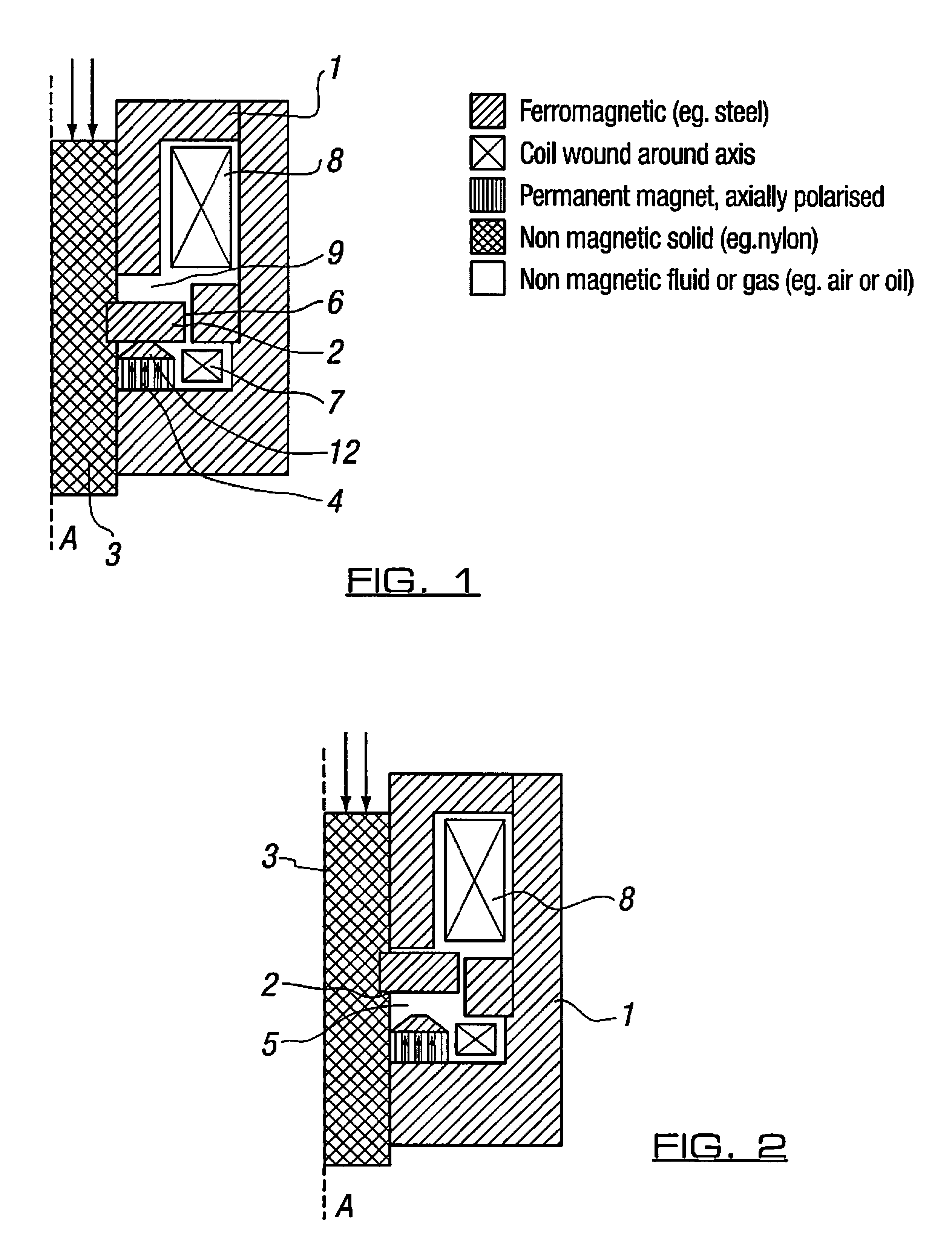
[0026]The actuator of FIG. 1 is symmetrical about an axis A and comprises a core 1 of steel or other ferromagnetic material and which may be formed from a plurality of components. A moving ferromagnetic component (“armature”) 2 is attached via a sliding non-magnetic body 3 to the valve spool or poppet or other element to be actuated.

[0027]A first magnetic circuit incorporates part of the core 1, a permanent magnet 4, an “axial” air gap 5 (“latch gap”, shown in FIG. 2), a “radial” air gap 6, and a first coil (“trigger coil”) 7.

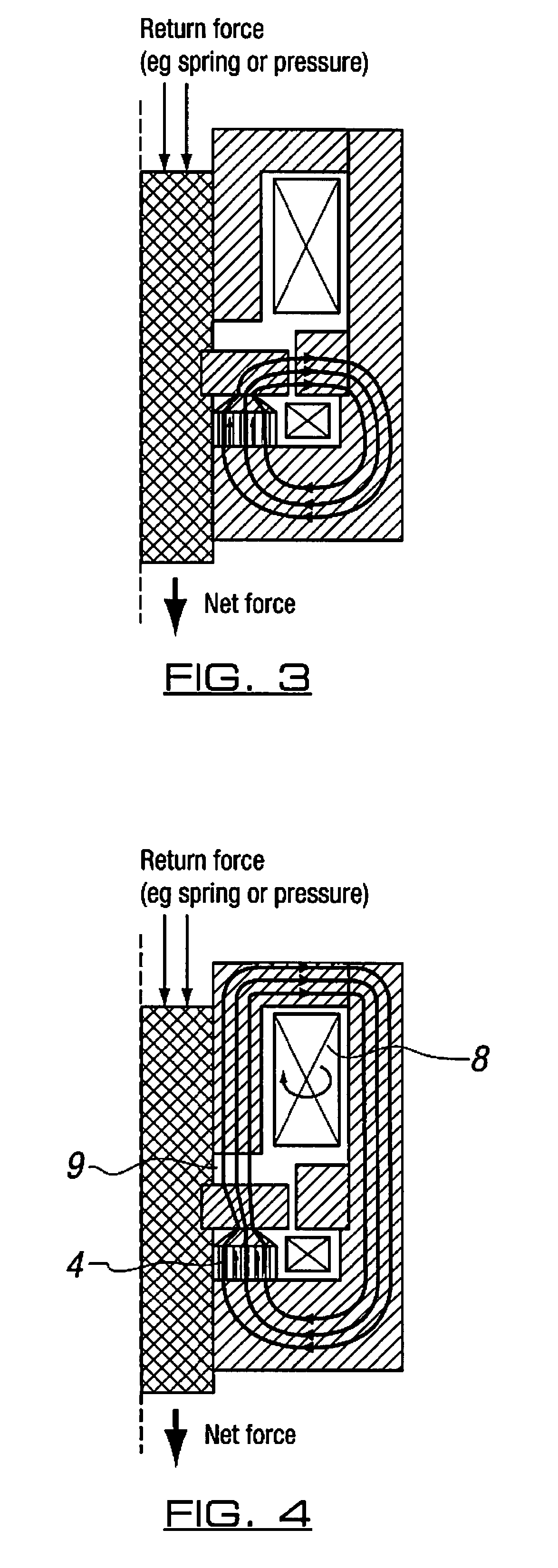
[0028]A second magnetic circuit incorporates part of the core 1, a second coil (“main coil”) 8 forming the solenoid, and an axial air gap (“main gap”) 9, and shares the radial air gap 6 with the first magnetic circuit.

[0029]The actuator holds the armature 2 in the position as shown in FIG. 1 by means of the permanent magnet 4. Flux from this magnet is concentrated to increase the holding force by means of a flux concentrating geometric feature 12 (preferably a ...


PUM


Abstract

An electromagnetic actuator comprises a core (1), a ferromagnetic component (2) movable in a gap (5) in the core, and a magnet (4) for attracting the component to one side of the gap. A flux concentrator (12) concentrates the magnetic flux on that side of the gap (5) and a solenoid (8) produces magnetic flux in the gap. A magnetic circuit of the solenoid is defined by part of the core (1), part of the gap (5) and by a further gap (6) between the ferromagnetic component (2) and the core (1). A demagnetiser (7) has a magnetic circuit defined by another part of the core (1), another part of the gap (5) and by the further gap (6). The demagnetiser is arranged to demagnetise the magnet (4) at least to the extent that the magnetic flux produced by the solenoid (8) is diverted from the flux concentrator (12) into the further gap (6) and the movable component (2) is movable away from the magnet (4) under the magnetic force of the solenoid (8).

Description

PRIORITY APPLICATIONS[0001]This application is a 371 application of International Application No. PCT / GB2007 / 001280 filed Apr. 3, 2007, which claims priority to United Kingdom Patent Application No. 0607072.6 filed Apr. 7, 2006. Each of the foregoing applications is hereby incorporated herein by reference.BACKGROUND TO THE INVENTION[0002]This invention relates to a solenoid actuator useful for application to hydraulic valves and to a valve arrangement incorporating such an actuator.[0003]Fluid power systems often rely upon solenoid-actuated valves to control the flow of fluid. It is often advantageous to be able to switch fluid from one path to another as fast as possible, such that the time spent in intermediate positions is minimised, hence minimising energy losses caused by pressure drops though the valve.[0004]Often such valves are constructed as single acting solenoids, whereby a ferromagnetic sliding member such as a spool or a poppet is attracted to an end face of a solenoid,...

Claims


Application Information

Patent Timeline
Patent Type & Authority Patents(United States)
IPC IPC(8): F16K31/02
CPCF02M51/0635H01F7/1646H01F7/081H01F2007/1888H01F7/1844H01F2007/1692
Inventor CALDWELL, NIALL JAMES
Owner ARTEMIS INTELLIGENT POWER
Why Eureka
Try Eureka