Retention bodies for fiber optic cable assemblies

a technology of fiber optic cable and assembly, applied in the direction of optics, instruments, optical light guides, etc., can solve the problems of unresolved need, difficult and/or time-consuming total exposure of strength elements for termination,

Active Publication Date: 2012-09-25
CORNING OPTICAL COMM LLC
View PDF58 Cites 36 Cited by
  • Summary
  • Abstract
  • Description
  • Claims
  • Application Information

AI Technical Summary

Problems solved by technology

Termination of fiber optic cables with a simple, reliable, and easy to assemble hardened connector for fiber to the subscriber applications as depicted in FIG. 1 is challenging for many reasons.
Thereby making total exposure of the strength elements for termination difficult and / or time consuming.
Thus, there is an unresolved a need for a robust fiber optic cable termination that is simple, reliable, and easy to assemble.

Method used


Image

  • Retention bodies for fiber optic cable assemblies
  • Retention bodies for fiber optic cable assemblies
  • Retention bodies for fiber optic cable assemblies

Examples


Embodiment Construction

[0037]Reference will now be made in detail to the preferred embodiments of the disclosure, examples of which are illustrated in the accompanying drawings. Whenever possible, like reference numbers will be used to refer to like components or parts.

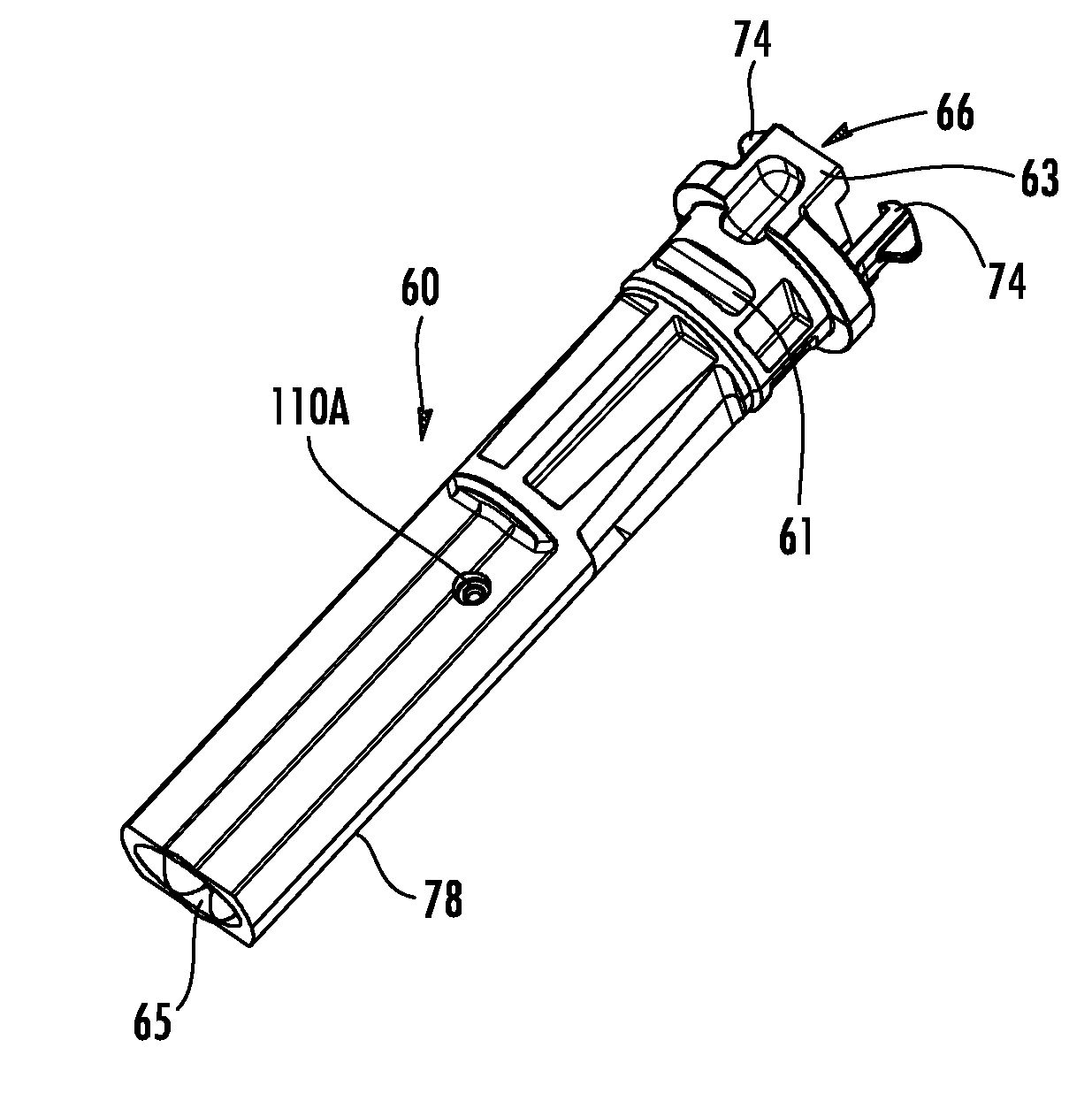
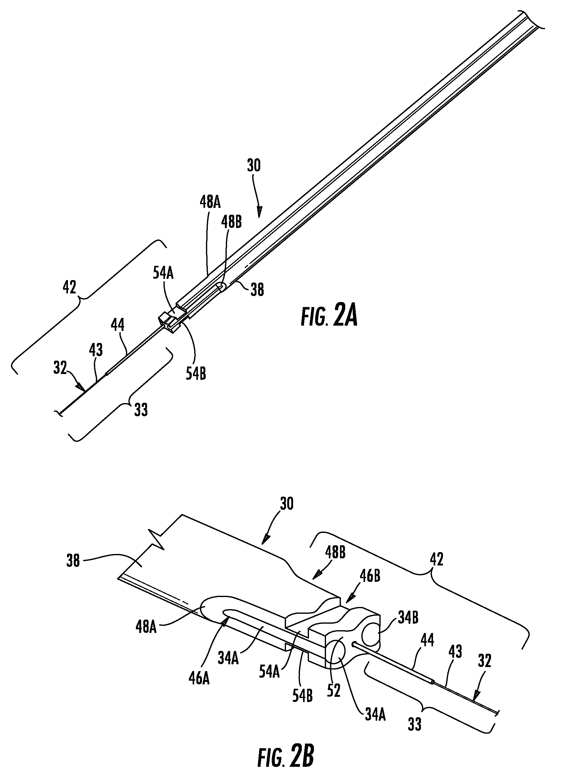
[0038]The embodiments described herein include fiber optic cable assemblies and related components, securing methods, and fiber optic cable preparation methods for securing a fiber optic cable to a retention body or the like, which may further form a fiber optic connector (i.e., termination of the fiber optic cable with a fiber optic connector). Disclosed methods and terminations prepare an end portion of a fiber optic cable for insertion into a retention body of a hardened fiber optic connector. Moreover, the concepts of the disclosure advantageously strain-relieve the end portion of the fiber optic cable without requiring totally exposing the strength components of the fiber optic cable while still providing a robust termination. Referenc...


PUM


Abstract

Retention bodies for securing a fiber optic cable thereto for optical connectorization are disclosed along with fiber optic cable assemblies. The fiber optic cable is inserted into a passage of the retention body and secured to the same using a bonding agent and / or a mechanical element. The rear end opening of the passage is configured for inserting and securing an end portion of the fiber optic cable having at least one strength component and a portion of a cable jacket. Additionally, the retention body has a buckling chamber disposed within the retention body passage for accommodating movement of optical fiber.

Description

RELATED APPLICATIONS[0001]The present application is a Continuation-In-Part of U.S. Ser. No. 12 / 241,346 filed on Sep. 30, 2008, the disclosure of which is incorporated by reference.BACKGROUND[0002]1. Field of the Invention[0003]The disclosure is directed to a retention body or other fiber optic cable supporting component configured to receive an optical fiber from a fiber optic cable as part of a fiber optic cable assembly. A buckling chamber is included and configured to store any excess optical fiber, such as due to retraction of an optical ferrule.[0004]2. Technical Background[0005]Optical fiber is increasingly being used for a variety of applications, including but not limited to broadband voice, video, and data transmission. Benefits of optical fiber use include extremely wide bandwidth and low noise operation. With the increasing and varied use of optical fibers, it is important to provide efficient methods of interconnecting optical fibers. Fiber optic connectors have been de...

Claims


Application Information

Patent Timeline
Patent Type & Authority Patents(United States)
IPC IPC(8): G02B6/36
CPCG02B6/3823G02B6/3887G02B6/3821G02B6/3885G02B6/3888G02B6/38875G02B6/3889
Inventor COLEMAN, CASEY A.THEUERKORN, THOMAS
Owner CORNING OPTICAL COMM LLC
Why Eureka
Try Eureka