
Smart lock system

a smart lock and key technology, applied in the field of electronic key systems and devices, can solve the problems of increasing the cost of traditional access control systems and methods, increasing the cost of traditional locks, and providing reliable and secure means, so as to achieve the effect of not having to spend the cost and technical effor

Inactive Publication Date: 2012-09-25
THE EASTERN COMPANY
View PDF25 Cites 29 Cited by
  • Summary
  • Abstract
  • Description
  • Claims
  • Application Information

AI Technical Summary

Benefits of technology

[0007]In one application of the present invention, a plurality of electronic locks is installed to control access to a plurality of secured areas—for example, supply cabinets in a classroom laboratory where a plurality of students complete a laboratory curriculum. Each newly reporting student among the plurality of students receives a key card programmed with a list of locks securing cabinets to which the student is permitted access. When a student completes their laboratory curriculum, or if the student loses their key card, the database, the key cards, and the locks are rapidly updated to reflect that the student no longer is permitted access. All the preceding is accomplished without incurring the capital costs and inconvenience associated with providing a wired network to each lock, and without the expense and technical effort associated with providing a wireless network between the locks and the database.

Problems solved by technology

However, the traditional access control systems and methods are increasingly costly as a function of the security provided.
Additionally, regardless of the level of security, traditional locks are very costly to properly maintain.
However, the exemplary systems, despite their commercial success, do not to our knowledge provide reliable and secure means for rapidly updating access permissions in a distributed security application, wherein individual locks are installed in various far-flung locations so that capital costs or physical constraints prohibit placing the individual locks in direct communication with a central database or bringing the locks to a central location for reprogramming.

Method used


Image

  • Smart lock system
  • Smart lock system
  • Smart lock system

Examples


Embodiment Construction

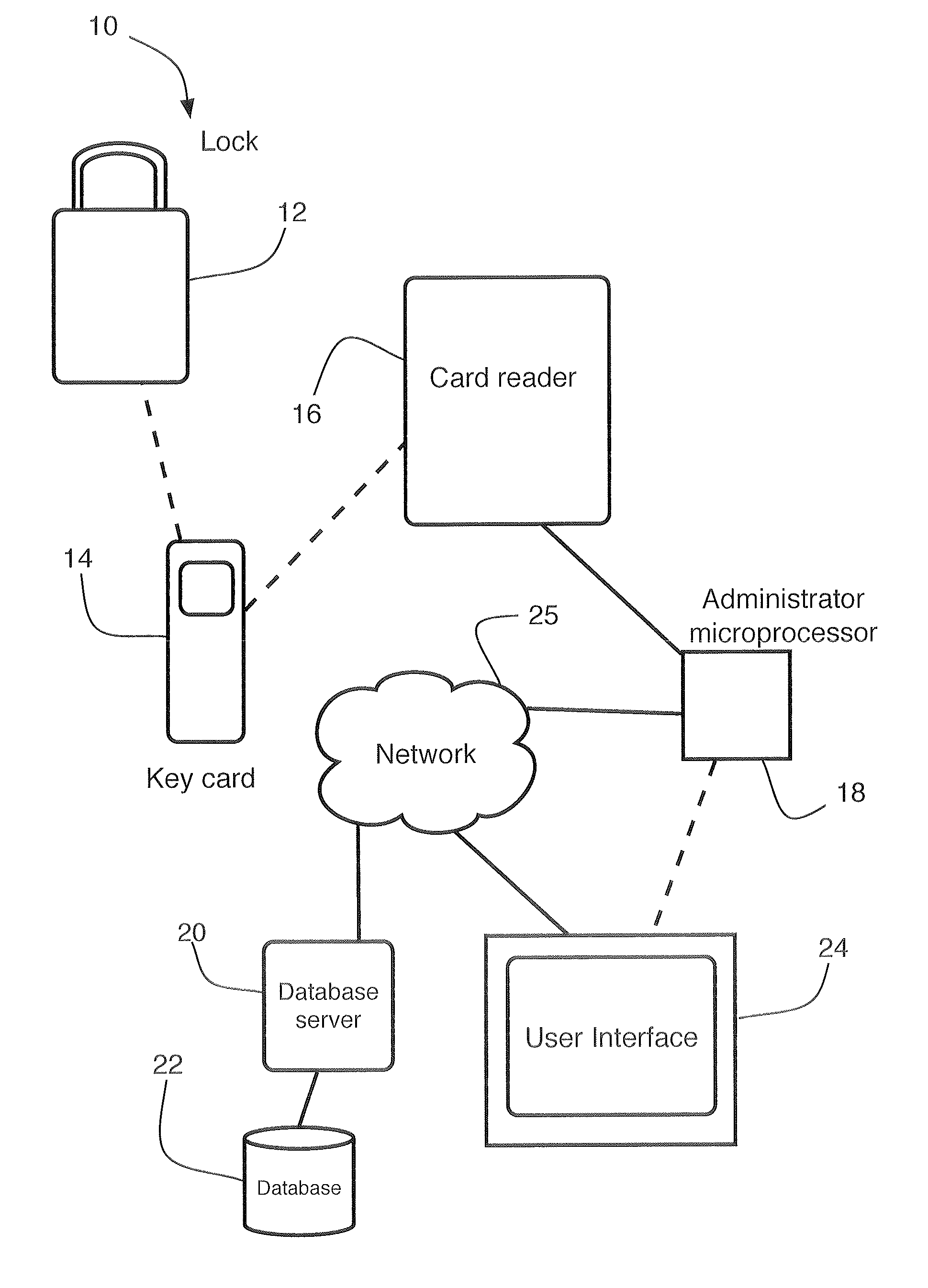
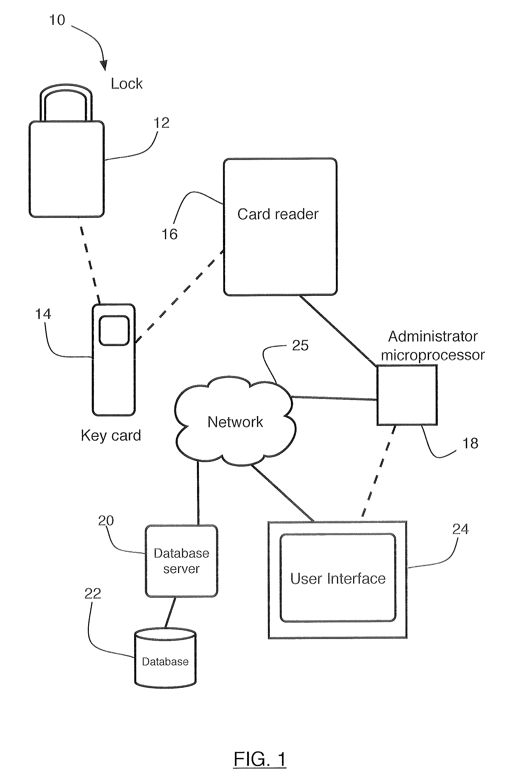
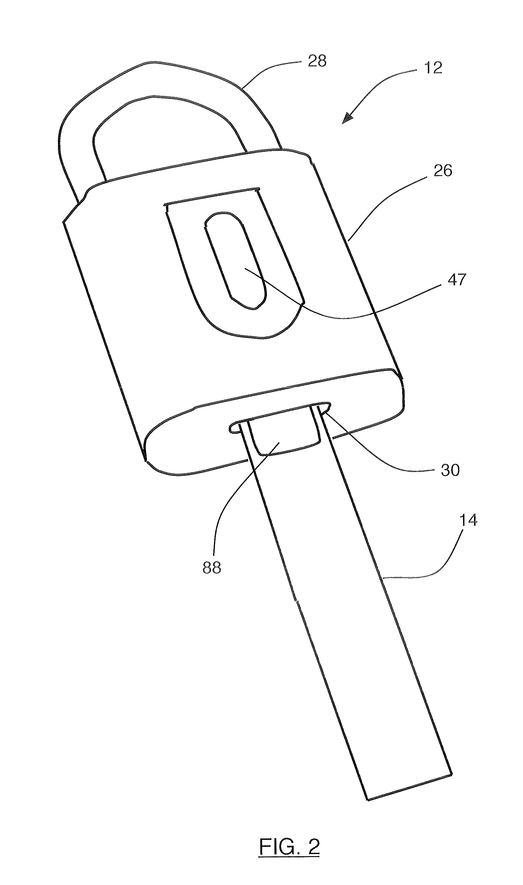
[0018]Referring to FIG. 1, one embodiment of the present invention provides a lock system 10 comprising a padlock 12, a key card 14, and a card reader 16. The key card 14 is portable and is removably engageable with the padlock 12 so as to provide and record access to an area secured by the system 10 through exchange of information between the lock 12 and the card 14. The card reader 16 is in communication with an administrator microprocessor 18 that is in communication with a database server 20 that maintains a database 22 for storing information about the system 10. The key card 14 is removably engageable with the card reader 16 so as to transfer information between the padlock 12 and the database 22 via the administrator microprocessor 18 and the database server 20. The administrator microprocessor 18 also is configured to provide instances of a user interface 24 for observation, control, and modification of the system 10 via a network 25. For example, the network 25 may be any o...


PUM


Abstract

An electronic access control and recording system includes a lock, a card reader, a key card configured to communicate with the lock and with the card reader, a database, and an administrator microprocessor configured to provide a user interface and to communicate with the database and with the card reader. At least one of the lock and the card contain a microprocessor and a non-volatile memory storing encrypted information. In use, the key card provides access to the lock and transfers the encrypted information between the lock and the database via the card reader and the administrator microprocessor. The administrator microprocessor provides a user interface for reviewing and administering the database. The user interface also provides account and password qualification for users.

Description

FIELD OF THE INVENTION[0001]The present invention relates to systems and devices for access control and, more particularly, to electronic key systems and devices for access control and monitoring.BACKGROUND OF THE INVENTION[0002]Traditional key padlocks or programmable mechanical locksets have been used to secure areas including buildings, rooms and cabinets. In these and other applications, access control systems and methods have been implemented to grant access only to authorized users and to update access permissions. The traditional locks have been developed over centuries to be sturdy and moderately difficult to bypass, and to function reliably without frequent inspection or maintenance. However, the traditional access control systems and methods are increasingly costly as a function of the security provided. Additionally, regardless of the level of security, traditional locks are very costly to properly maintain. For example, when a former user no longer is authorized, or when...

Claims


Application Information

Patent Timeline
Patent Type & Authority Patents(United States)
IPC IPC(8): G05B19/00G06F7/00B60R25/00G05B23/00
CPCE05B41/00E05B47/06E05B67/00G07C9/00309G07C9/00015G07C2009/00793G07C9/21
Inventor PICCIRILLO, JAMES S.HOOPER, WAYNE J.LAMOURINE, CHRISTOPHER E.YUDELSON, DAVID A.
Owner THE EASTERN COMPANY
Learn More