Damaged bolt and screw removing devices

a technology of bolt and screw, which is applied in the direction of wrenches, manufacturing tools, transportation and packaging, etc., can solve the problems of device not being able to remove a fastener having a slotted surface configuration, device still needing considerable power to impart the rotational torque, and the german tool cannot be used to remove a fastener. , to achieve the effect of effectively extracting wayward fasteners, enhancing the bite of the bit into the interior surface, and low torqu

Active Publication Date: 2012-10-02
COMBINED PRODS
View PDF51 Cites 15 Cited by
  • Summary
  • Abstract
  • Description
  • Claims
  • Application Information

AI Technical Summary

Benefits of technology

[0011]An advantage of the invention is that the different cutting edge angles enhance the bite of the bit into the interior surfaces of the fastener. In one such embodiment, the cutting edges contain serrations which may be located substantially perpendicular to the longitudinal axis of the cutting edge to provide additional purchase of the fastener. The serrations allow the bit to effectively extract wayward fasteners at torque speeds as low as 0.25 RPM, and as high as typical RPM values of commercially available electric screw drivers and power tools. Hand-actuated screw drivers, by comparison, are typically turned one quarter turn per wrist roll such that 30 RPM is typical for a non-powered hand tool.
[0012]In yet another embodiment, the invention comprises a left-handed countersink drill bit containing serrations which extend from a cutting edge of the bit. This drilling feature of the remover provides that more interior surfaces of the fastener be made available to the cutting edges of the serrations, so as to allow the threaded cavity of the workpiece to remain intact as the fastener is removed.
[0013]In still another embodiment, a plurality of generally longitudinally-extending serrations are interposed between axially spaced steps in a drill bit. These serrations extend in a left-hand cutting fashion from a cutting edge of the bit. This embodiment can be utilized to extract fasteners having a myriad of different shank diameters.
[0014]In another embodiment, the tip region of the bit includes a recess disposed substantially along the longitudinal axis of the bit, which allows the bit to remove a security fastener having a post.
[0015]It is therefore an object of the present invention to provide a broken bolt / screw remover that overcomes many of the disadvantages of the prior art.
[0016]It is a further object of the present invention to provide a broken bolt / screw remover which requires only low levels of torque to extract a fastener.

Problems solved by technology

However, the more a fastener is used, the more likely that its head becomes rounded off, worn, broken, or otherwise rendered useless.
However, such devices still require considerable power to impart the rotational torque necessary to “bite” into the fastener and begin left-handed extraction.
Accordingly, the German tool cannot be used to remove a fastener having a slotted surface configuration unless the fastener includes a recess with a depth sufficient to allow the two cutting edges to be inserted therein.
Otherwise, the slotted head fastener would be damaged during removal.

Method used


Image

  • Damaged bolt and screw removing devices
  • Damaged bolt and screw removing devices
  • Damaged bolt and screw removing devices

Examples


Embodiment Construction

[0062]While this invention is susceptible to embodiments in many different forms, there are shown in the drawings and will herein be described in detail, preferred embodiments of the invention with the understanding that the present disclosures are to be considered as exemplifications of the principles of the invention and are not intended to limit the broad aspects of the invention to the embodiments illustrated.

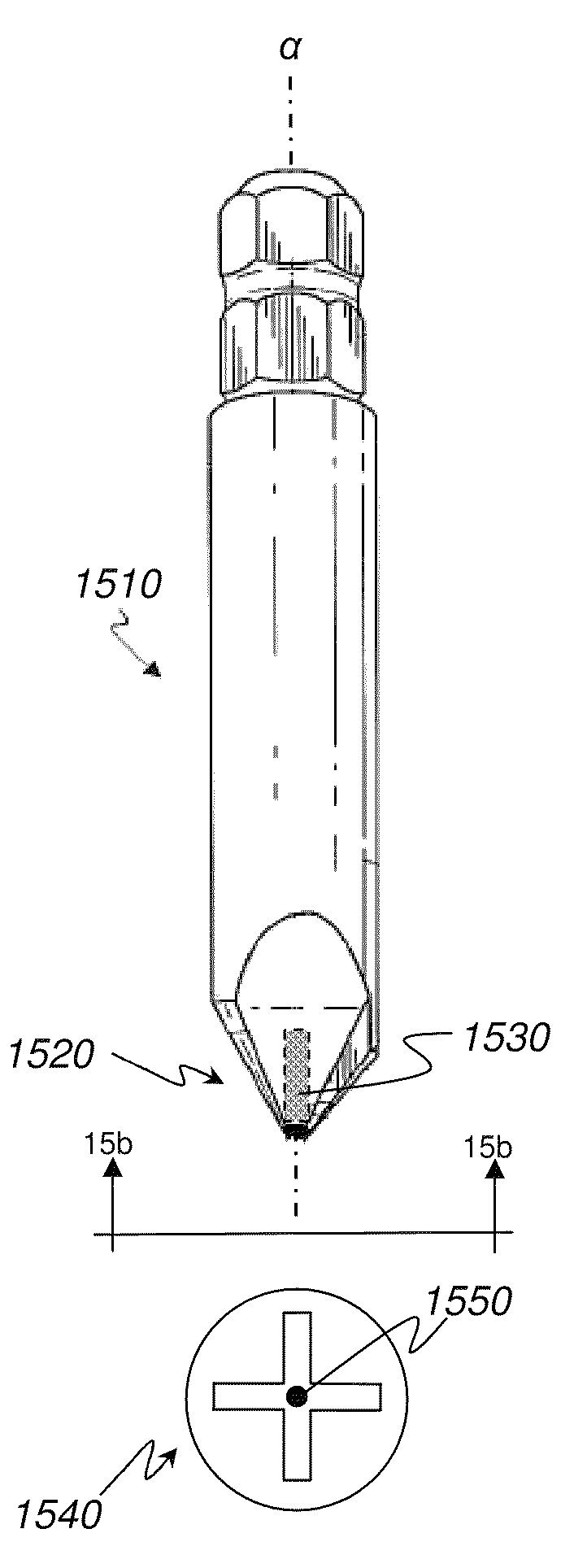
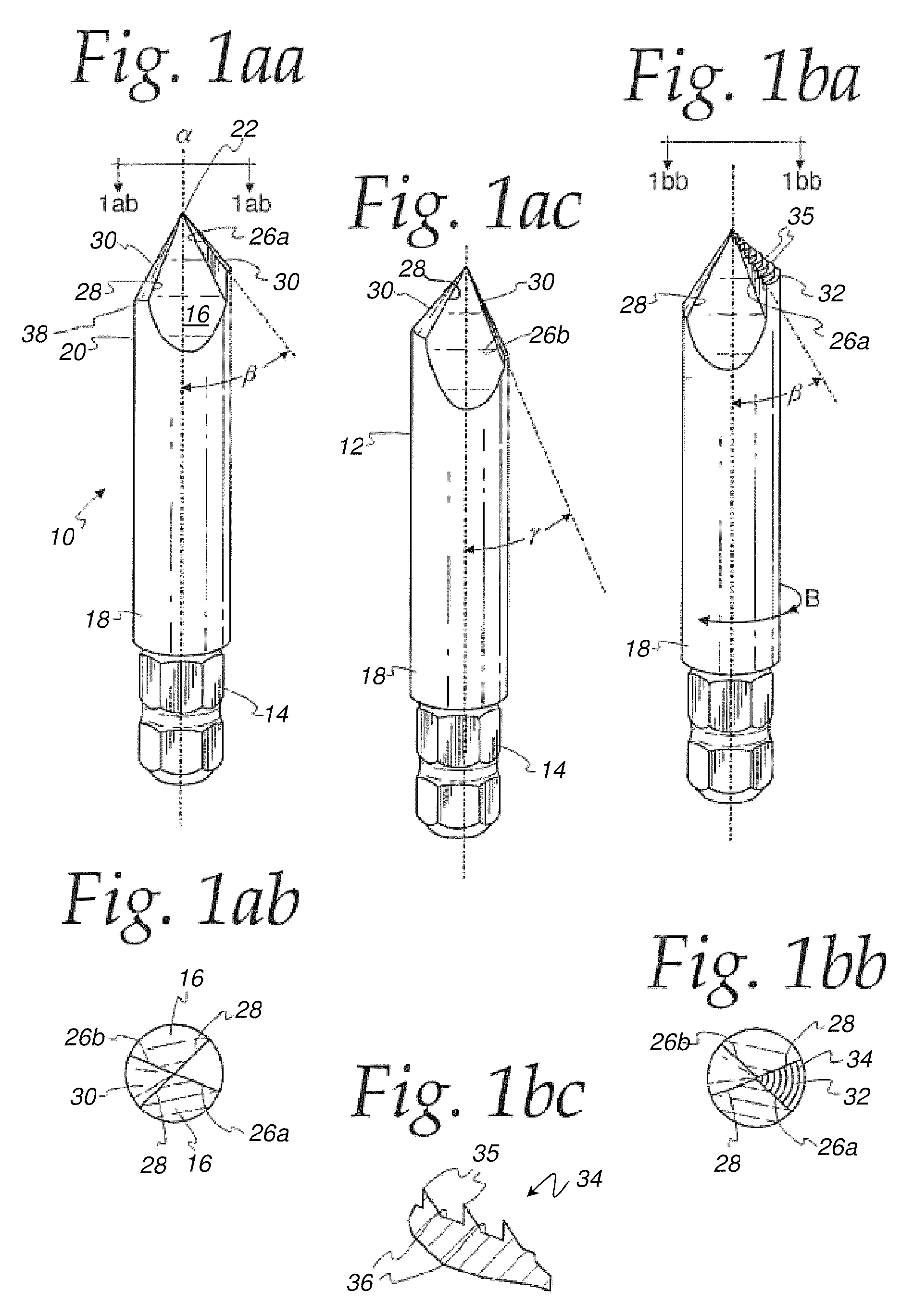
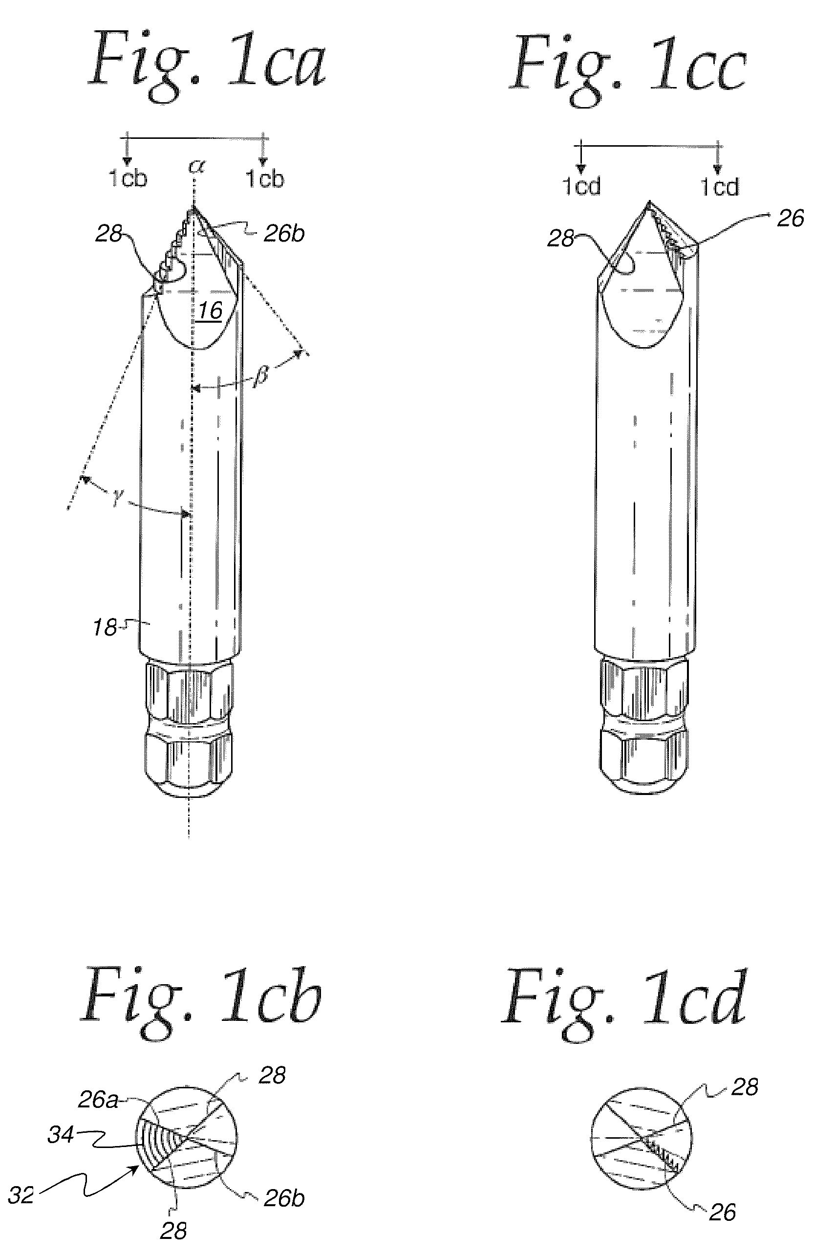
[0063]FIG. 1aa provides salient features of the invented bit, the bit designated as numeral 10. The bit 10 generally comprises a shaft 12 having a periphery 18 and a first end 20 terminating in a tip region 22. While the tip region 22 is depicted as generally pointed, a non-pointed tip region may be utilized, such as a standard split-tip whose cutting surfaces are not coplanarly aligned with one another, or with the tip region. Being that the split-tip configuration minimizes and prevents “walk out” of the bit from the workpiece, it serves as a means for maintaining the bit...


PUM


Abstract

A bit for removing a broken security fastener having an elongated shaft with a longitudinal axis. The shaft has a first end and a second end. The first end terminates in a tip region having a recess for receipt of the post of the security fastener, the recess being disposed substantially along the longitudinal axis. The second end of the shaft is configured to be received by the chuck of a tool which provides rotational torque.

Description

RELATED APPLICATIONS[0001]This patent application is a continuation-in-part of U.S. patent application Ser. No. 11 / 985,099 filed on Nov. 14, 2007, which in turn is a continuation-in-part of U.S. patent application Ser. No. 11 / 255,424 filed Oct. 22, 2005, now abandoned, which in turn is a continuation-in-part of U.S. patent application Ser. No. 10 / 831,391 filed Apr. 23, 2004 and issued as U.S. Pat. No. 6,978,697, which claims priority benefit to the filing date of U.S. Provisional Patent Application No. 60 / 465,506 filed on Apr. 25, 2003; the content of these applications is expressly incorporated herein by reference.FIELD OF THE INVENTION[0002]The present invention relates to the field of hardware tool bits, and more particularly, to a device for removing damaged fasteners still embedded in, or otherwise engaged with, a workpiece.BACKGROUND OF THE INVENTION[0003]The use of fasteners, such as screws, bolts, and other threaded joining devices, continues to increase. However, the more a...

Claims


Application Information

Patent Timeline
Patent Type & Authority Patents(United States)
IPC IPC(8): B25B13/50
CPCB23B51/009B23B51/00B23B51/02B25B27/18B23B2251/04B23B2251/48B23B2251/082B23B51/10B23B51/0081B23B51/0009B23B2251/087B23B2251/14B23B51/00035
Inventor KOZAK, BURTONKOZAK, IRA
Owner COMBINED PRODS
Why Eureka
Try Eureka