

Dual actuator drive assembly with synchronization shaft
- Summary
- Abstract
- Description
- Claims
- Application Information
AI Technical Summary
Benefits of technology
Problems solved by technology
Method used
Image

Examples
Embodiment Construction
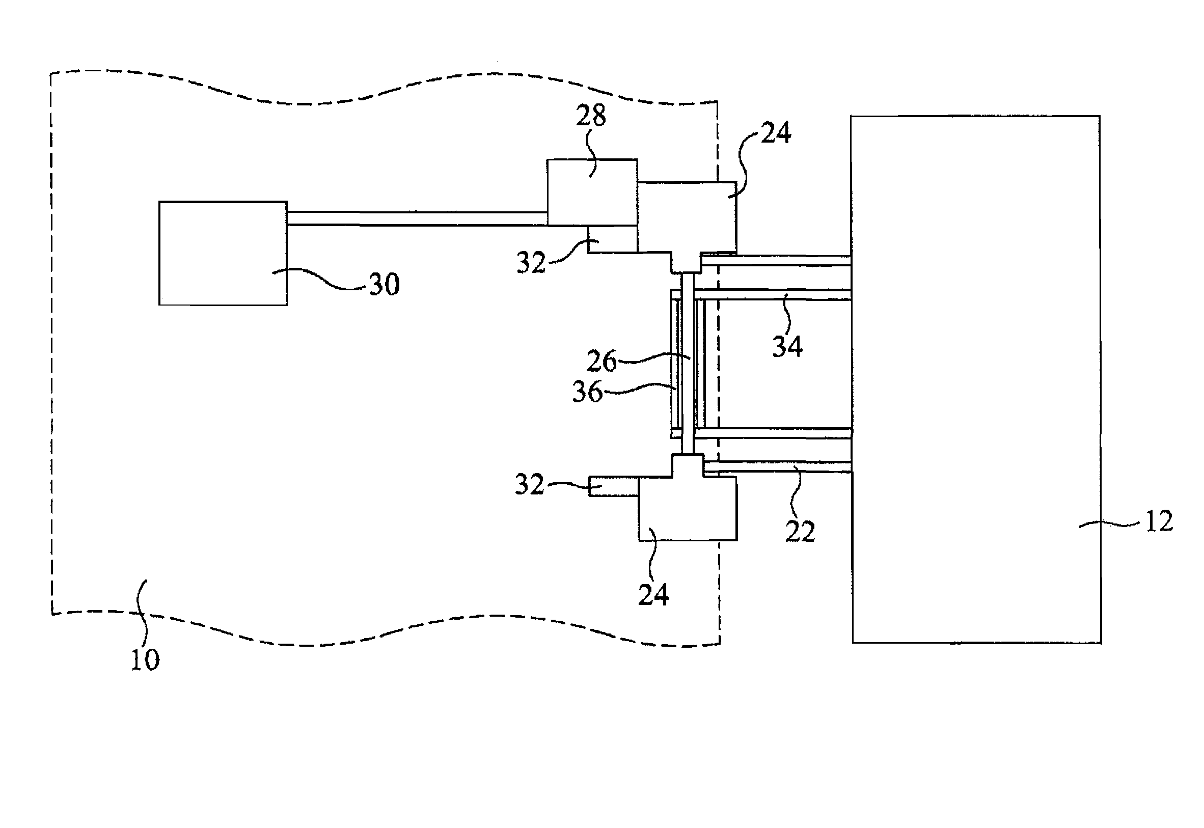
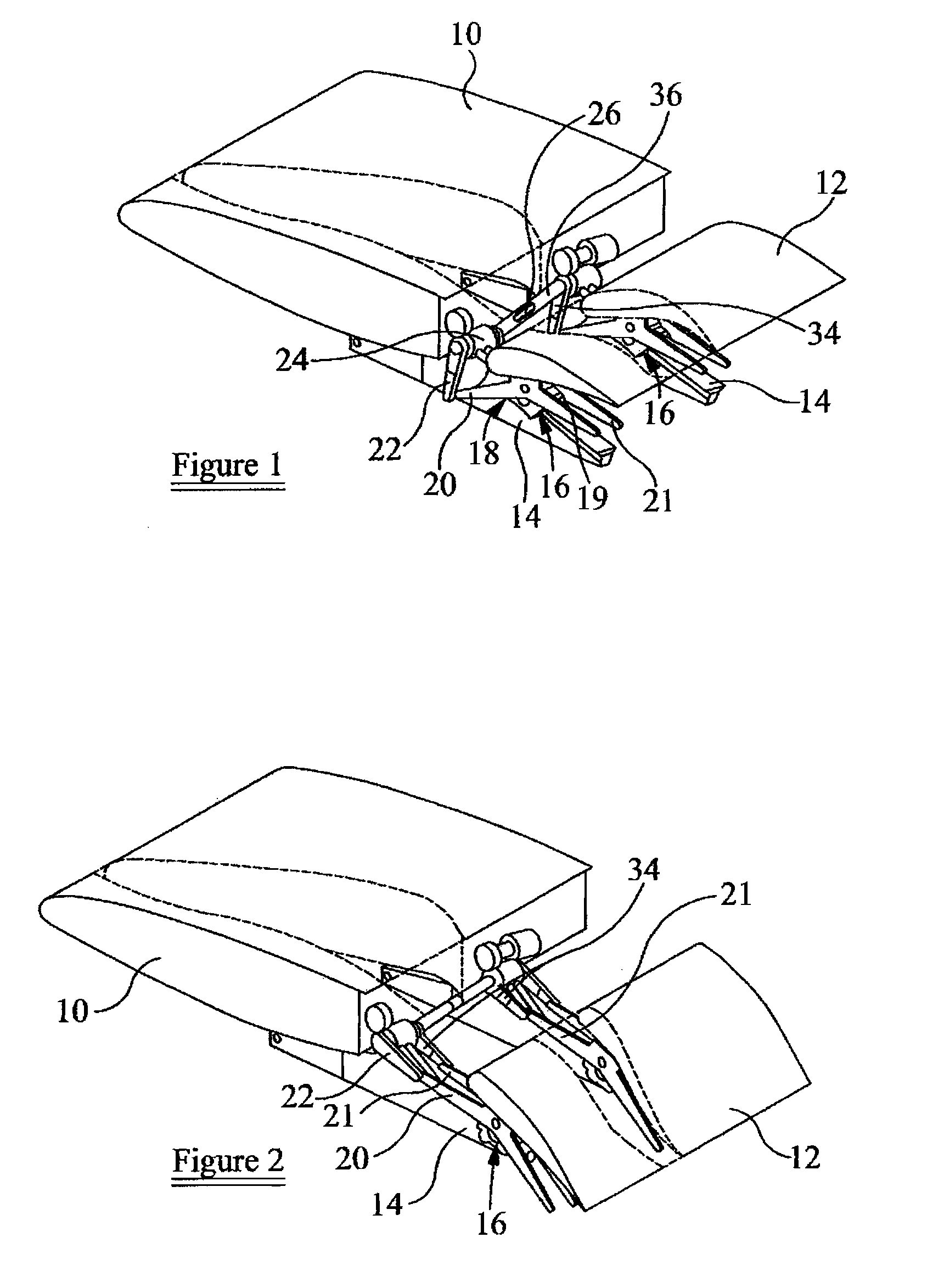
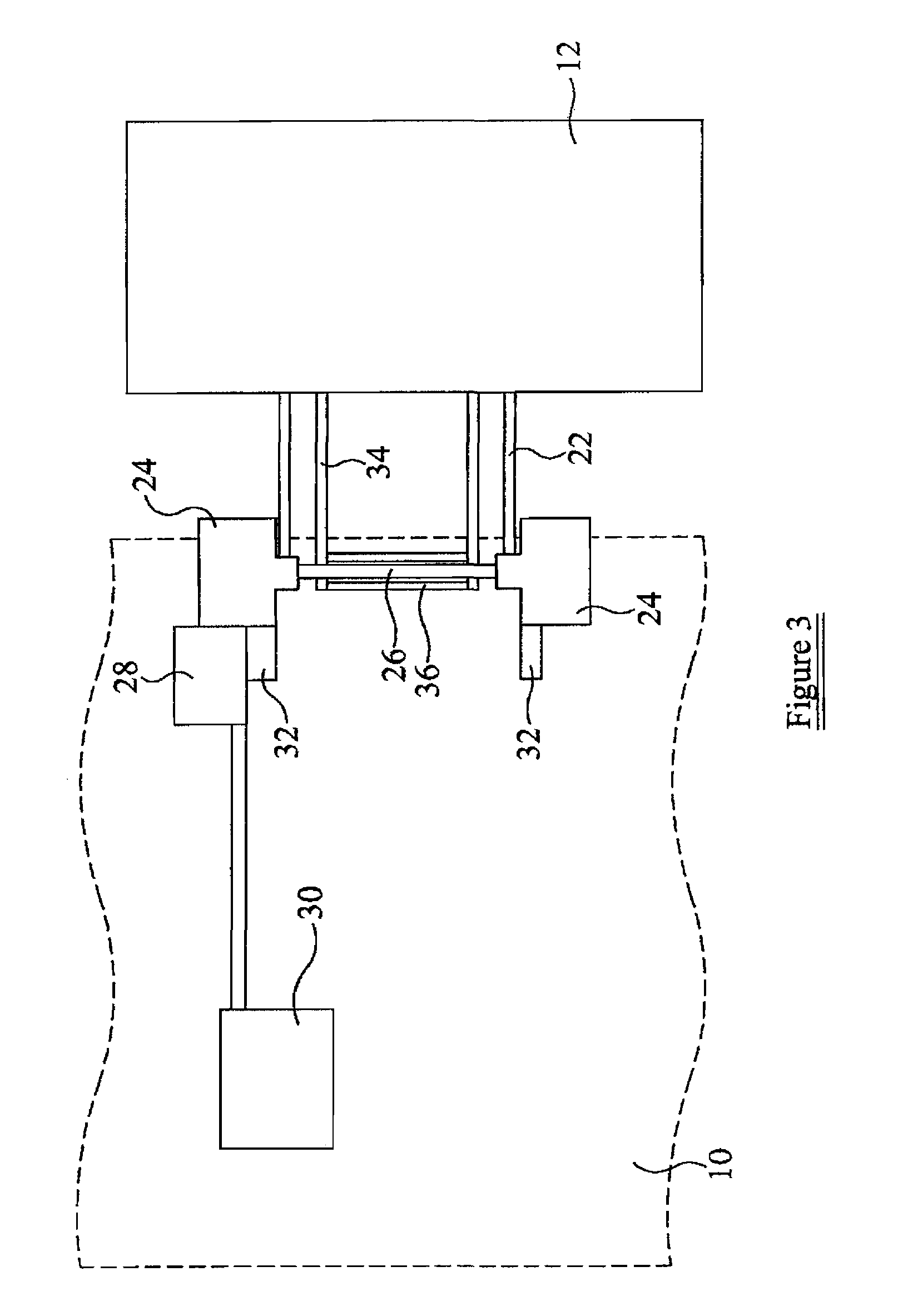
[0015]FIGS. 1 and 2 illustrate part of an aircraft wing 10 with which a trailing edge control surface or flap 12 is associated. FIG. 1 illustrates the wing 10 with the flap 12 in a stowed position, FIG. 2 illustrating the flap 12 in a deployed position. The flap 12, which may be several meters in length, is secured to the wing 10 by first and second mounting arrangements, each comprising a support track 14 secured to the wing 10 and along which a follower or trolley 16 can travel. The respective followers 16 are pivotally mounted to the flap 12 at spaced locations along its length by pivotal mounting arrangements 18. As illustrated, a pivotal mounting arrangement 18 includes an elongate arm or link 20 which is pivotally connected to an output member in the form of a link 22 angularly movable by an actuator 24 which is driven for angular movement by a drive shaft 26. By comparing FIG. 1 with FIG. 2, it will be apparent that rotation of the drive shaft 26 causes angular and translatio...
PUM
 Abstract
Description
Claims
Application Information