Soldering iron stand

a technology of soldering iron and stand, which is applied in the direction of machine supports, soldering apparatus, manufacturing tools, etc., can solve the problems of unfavorable temperature management, uncomfortable metallic sound when a soldering iron is put, and heat accumulation in the grip portion of the soldering iron

Active Publication Date: 2012-10-02
HAKKO CO LTD
View PDF12 Cites 4 Cited by
  • Summary
  • Abstract
  • Description
  • Claims
  • Application Information

AI Technical Summary

Benefits of technology

[0037]An operator can insert the soldering tip of the soldering iron into the metal wool container through the cleaning window to efficiently clean the soldering tip using the strip-shaped metal wool in the container. During this operation, the soldering tip can be scraped by the scraping portion provided along the lower edge of the cleaning window to further efficiently scrape off solder residue upon the soldering tip. In the above aspect, the scraping portion is preferably a raised region extending along the lower edge of the cleaning window. The raised region may be formed in various shapes, such as a linear shape, a curved shape, a wave shape, and, in cross-section, a triangular shape.

Problems solved by technology

Thus, in many times, uncomfortable metallic sound occurs when a soldering iron is put on the soldering holder during the use of the conventional soldering iron stand disclosed in the Prior Art Document 1 due to the friction between the soldering iron and the soldering iron holder.
In this case, however, heat is liable to accumulate in a grip portion of the soldering iron.
This causes a new problem that a temperature management becomes difficult.

Method used


Image

  • Soldering iron stand
  • Soldering iron stand
  • Soldering iron stand

Examples


Embodiment Construction

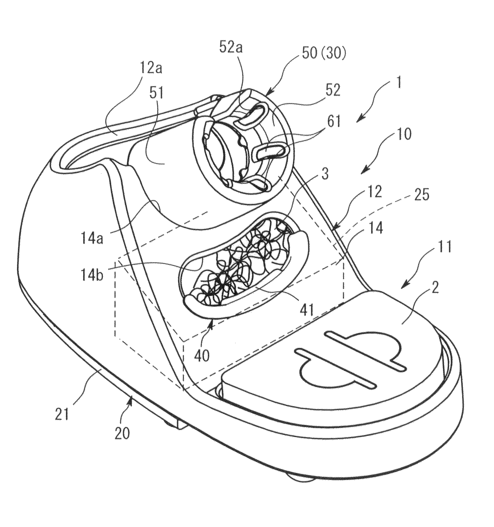
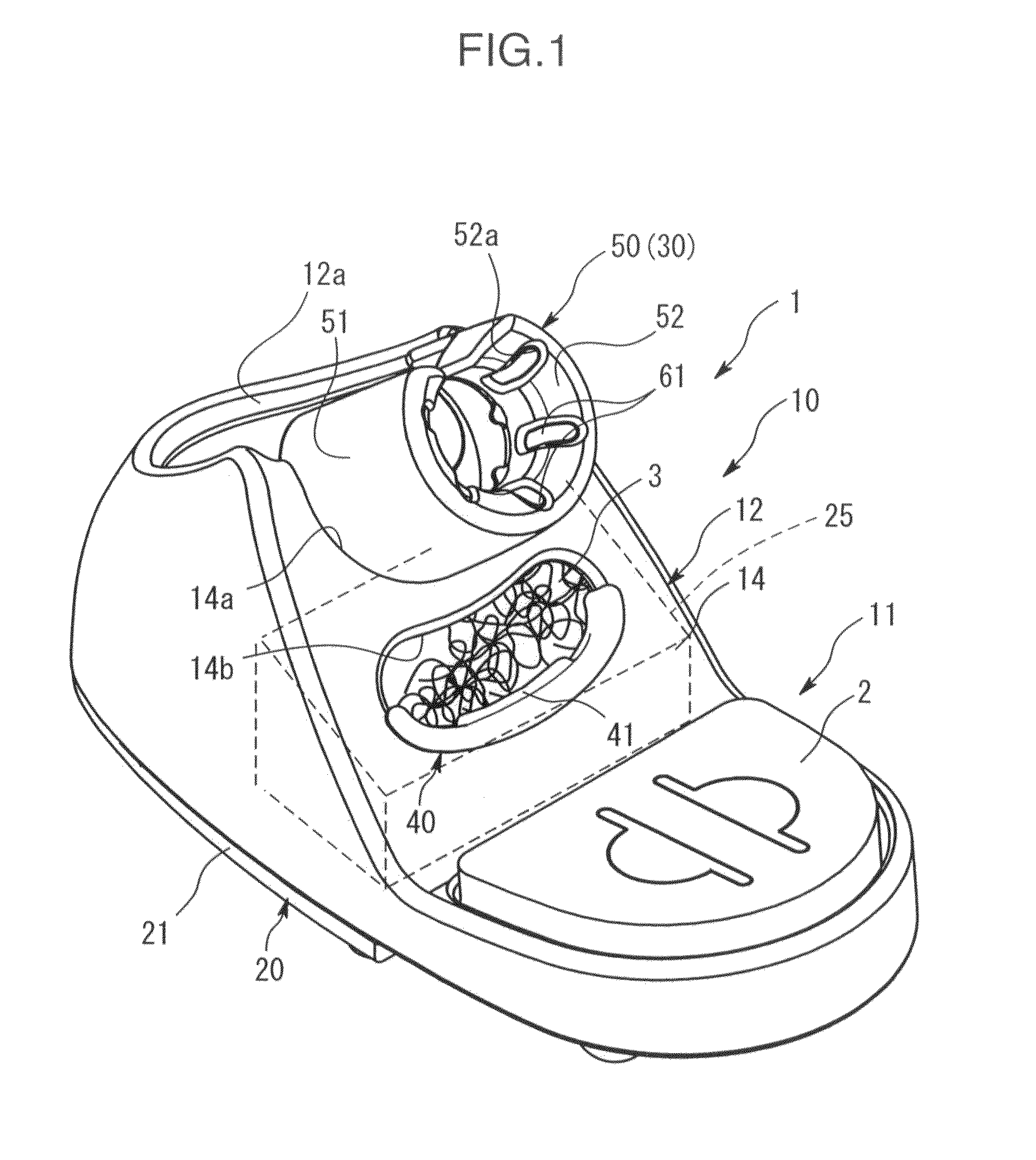
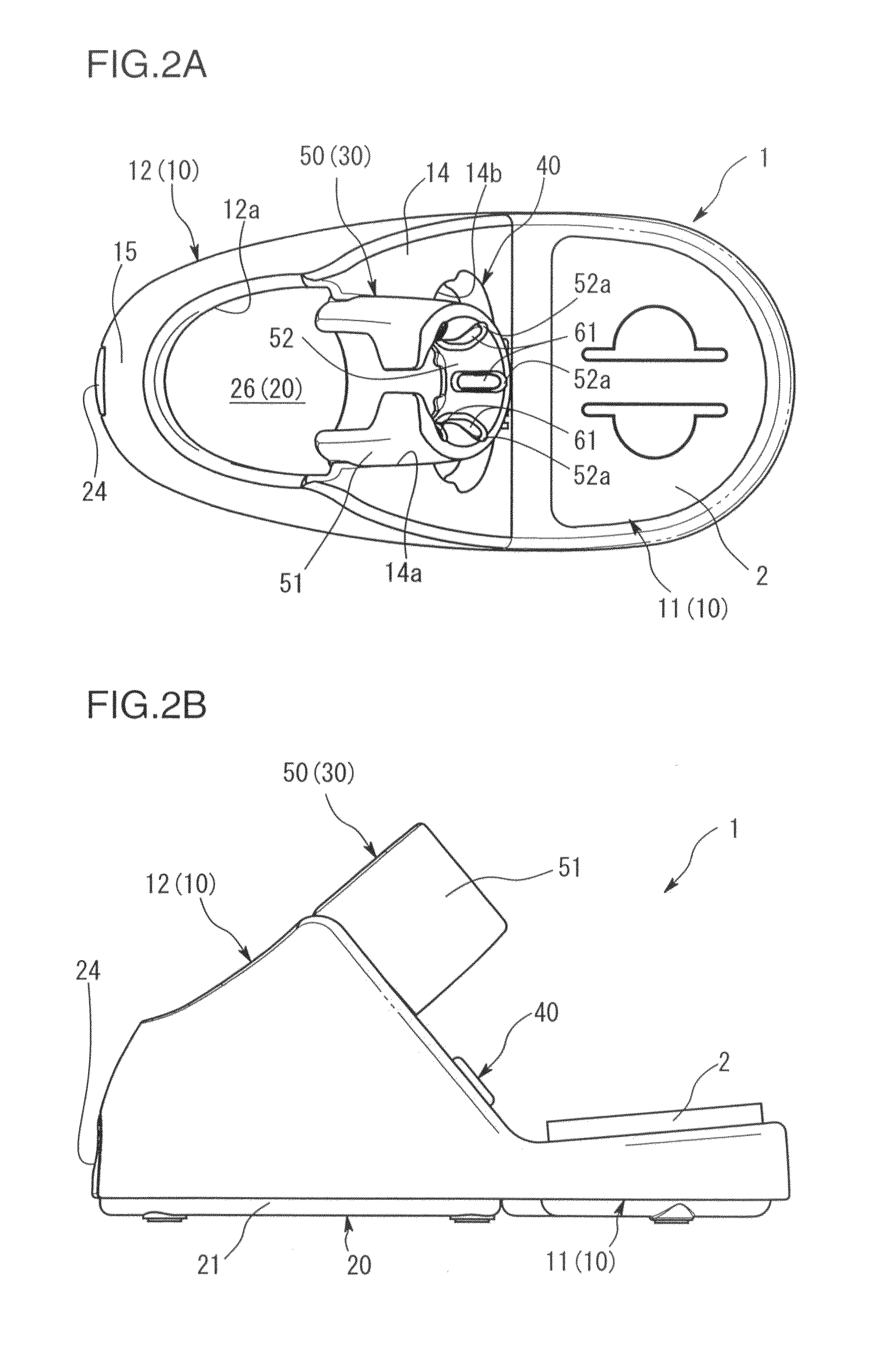
[0026]According to an embodiment of the present invention, a soldering iron stand comprising a stand base and a soldering iron holder. The soldering iron holder is provided on an upper portion of the stand base, and formed to have a curved surface for receiving thereon a soldering iron to be held by the stand base. The soldering iron holder has a plurality of recesses or cavities formed therein and arranged in a circumferential direction of the curved surface, each of the recesses being provided with a heat-resistant elastic member.

[0027]The soldering iron comes into slide contact with the curved surface of the soldering iron holder when the soldering iron is inserted into the soldering iron holder to put the soldering iron on the stand. The vibration of the soldering iron holder which would occurs when the soldering iron is inserting will be absorbed and / or dampened by the heat-resistant elastic member. This prevents the noise which would otherwise be made in a conventional solderi...


PUM


Abstract

A soldering iron stand comprises a stand base, and a soldering iron holder provided on an upper portion of the stand base and formed to have a curved surface for receiving thereon a soldering iron to be held by the stand base. The soldering iron holder has a plurality of recesses formed therein and arranged in a circumferential direction of the curved surface. Each of the recesses is provided with a heat-resistant elastic member.

Description

CROSS-REFERENCE TO RELATED APPLICATION[0001]This application claims the benefit of U.S. Provisional Application No. 61 / 110,503, filed Oct. 31, 2008, which is incorporated herein by reference in its entirety. This application claims foreign priority to Japanese Application No. P2008-280823, filed Oct. 31, 2008, which is incorporated herein by reference in its entirety.BACKGROUND OF THE INVENTION[0002]1. Field of the Invention[0003]This invention relates generally to a soldering iron stand.[0004]2. Description of the State of the Art[0005]Soldering techniques are a cornerstone of the electric and electronic industries, and technological advances therein have been amazing.[0006]Along with industrial growth, soldering for a large number of electric / electronic circuit boards has been increasingly dominated by soldering using an automatic machine free of human power, i.e., a flow-soldering bath and a reflow-soldering furnace. However, there inherently remains a manual soldering task using...

Claims


Application Information

Patent Timeline
Patent Type & Authority Patents(United States)
IPC IPC(8): D06F5/00
CPCB23K3/027B23K3/029B23K3/08B23K2101/36
Inventor TERAOKA, YOSHITOMO
Owner HAKKO CO LTD
Why Eureka
Try Eureka