Method and apparatus for loading, detecting, and monitoring channel-associated optical signals

a channel-associated identification and channel-associated technology, applied in the field of optical communication, can solve the problems of not taking appropriate measures, difficult to construct a telecommunication-level optical transmission network that can be comparable, and cannot realize supervisory control over the quality or performance of optical signals, so as to reduce the power spectrum density reduce the interference of channel-associated identification signals, and less interference with optical service signals

Active Publication Date: 2012-10-02
HUAWEI TECH CO LTD
View PDF21 Cites 6 Cited by
  • Summary
  • Abstract
  • Description
  • Claims
  • Application Information

AI Technical Summary

Benefits of technology

[0018]The present invention provides a method and an apparatus for loading channel-associated optical signals, in which, a channel-associated signal is identified with a spread spectrum code in electrical domain, and the spectrum width of channel-associated signal is spread, so that the power spectrum density of the channel-associated identification signal is reduced, thereby reducing the interference of the channel-associated identification signal to optical service signals. With the same modulation depth, the channel-associated identification signal after being spectrum-spread has less interference to optical service signals; after being modulated to an optical service signal at respective loading points separately, the channel-associated identification signals are transmitted in the optical channel along with the optical signal. At any downstream detecting point, passing optical signals can be converted through photoelectric conversion, and the channel-associated identification signals are de-spread. By detecting the channel-associated signals, it is possible to learn about whether the upstream loading point works normally, whether the optical channel operates normally, etc., and thereby to find possible failures, solve problems, and monitor quality parameters of optical signals in real time, and improve reliability of the optical signal transmission.
[0019]According to the method for detecting a channel-associated optical signal provided by the present invention, the channel-associated signal of a corresponding loading point can be detected at a downstream detecting point; by processing the de-spread channel-associated signal, the working state of the upstream loading point and the state of network between the loading point and the detecting point can be judged according to the power component of the channel-associated signal, so as to attain the object of monitoring network performance by means of monitoring the channel-associated signal; in addition, the channel-associated signal can also carry overhead information, so that the transmission of channel-associated overhead information can be realized.
[0020]The apparatus for monitoring channel-associated optical signals is provided so that the channel-associated signal from the upstream loading point can be obtained, the upstream loading point and the state of network can be monitored, a passing optical signal can be loaded with a channel-associated signal of a loading point, the loading point can be monitored at the downstream detecting points, and therefore the reliability of optical signal transmission can be improved.

Problems solved by technology

Because of the transparency of optical signals, no channel-associated overhead information can be carried, and therefore one can not monitor the quality of optical signals in the whole course and thus one can not take appropriate measures that depend on the quality of the optical signals; and one can not detect the sources and destinations of the optical signals, avoid possible wrong associations in optical signals, reroute the optical signals, or perform any other processing on the optical signals according to the channel-associated overhead of optical signals.
As a result, it is difficult to construct a telecommunication-level optical transmission network that can be comparable to electric signal transmission networks.
However, the out-of-band OSC can only carry out routing and protective switching over optical signals, but cannot realize supervisory control over quality or performance of optical signals.
Therefore, it is unable to determine whether the quality of optical signals meets requirements.
The out-of-band OSC only transmits part of overheads and it is unable to determine whether the rerouting of optical signals by the reconfigurable devices actually accomplishes channel selection actions specified for the optical signals; and in addition, failure of the out-of-band OSC itself will also trigger processing on optical signals.
Even though reliability of the out-of-band OSC can be increased by means of a backup strategy, this will bring additional cost and complexity.
Although this method can realize monitoring of the quality of the wavelength signal, it has some disadvantages as follows: 1. Different wavelengths must be identified with different frequencies, and the frequency interval must be greater than the frequency resolution of the monitoring point, as a result, the available identification signals are very limited; 2. Although the low-frequency interference signal has a relatively little effect on the main optical channel, it still has some effect on the quality of the wavelength signal; 3. The corresponding relationship between the wavelength signal and the low-frequency interference signal must be configured in advance; otherwise it will be difficult to know which channel of the wavelength signal is monitored; 4. In this method, the optical signals cannot carry channel-associated overhead; protective switching, other channel selection commands and other indication information must be settled through other methods.
However, that method still has the following disadvantages: 1. The energy of the low-frequency signal is relatively concentrated, and still has some effect on the wavelength signal; 2. The corresponding relationship between frequency identifier and wavelength still has to be configured in advance, in order to ascertain to which channel the wavelength signal detected by the monitoring point belongs; 3. The optical signals cannot carry channel-associated overhead information; and therefore protective switching, channel selection commands and other indication information have to be settled through other methods.
However, it does not solve the problems of optical signal quality monitoring and differentiation among different identifiers.
None of the above mentioned prior arts meets the above requirements.
Furthermore, in order to avoid problems, e.g. that the modulation depth of optical service signals modulated by a channel-associated identification signal is insufficient, the channel-associated signal monitoring device can carry out feedback control over the optical signal modulated by the channel-associated signal monitoring device itself.

Method used


Image

  • Method and apparatus for loading, detecting, and monitoring channel-associated optical signals
  • Method and apparatus for loading, detecting, and monitoring channel-associated optical signals
  • Method and apparatus for loading, detecting, and monitoring channel-associated optical signals

Examples


Embodiment Construction

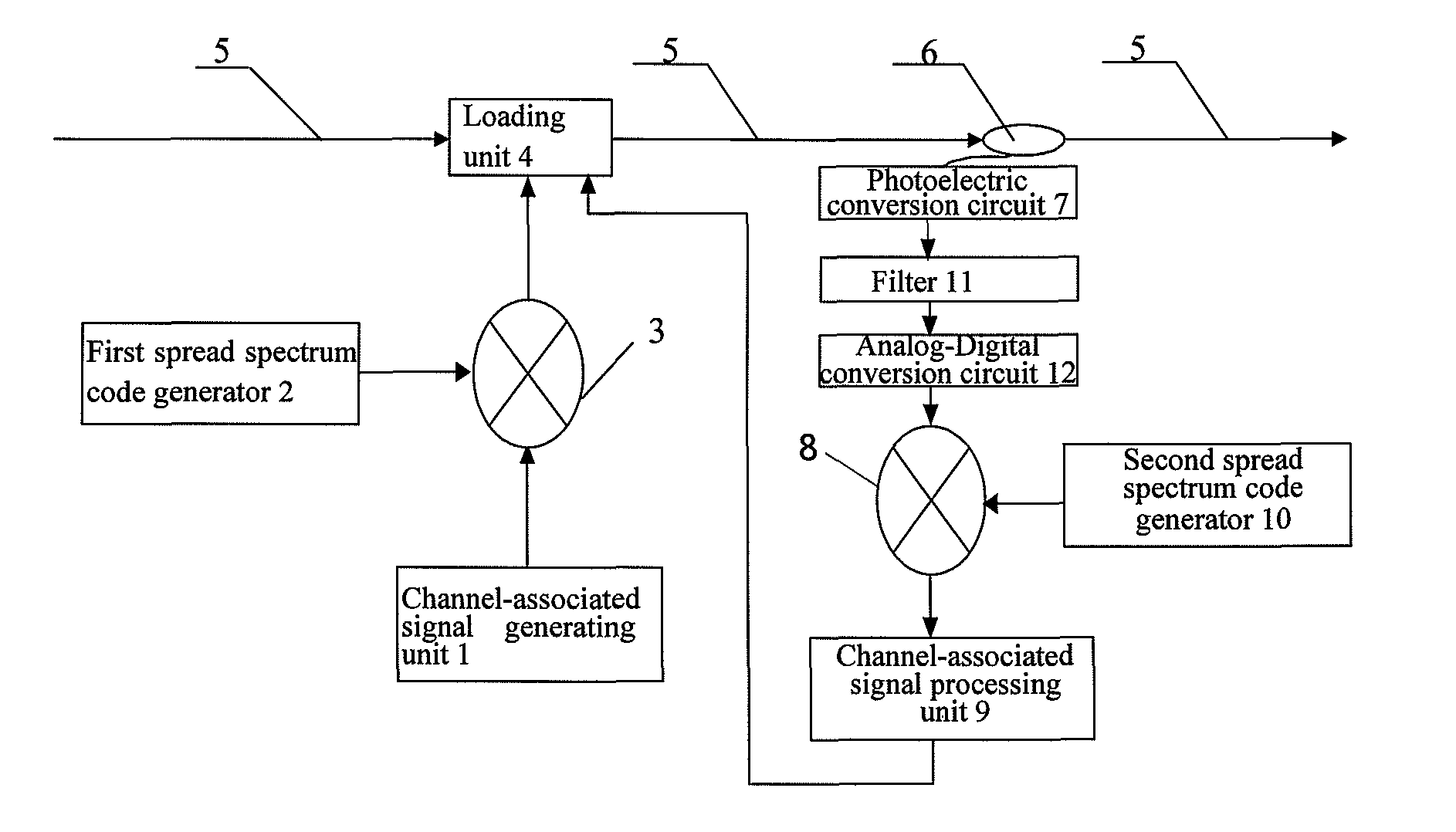
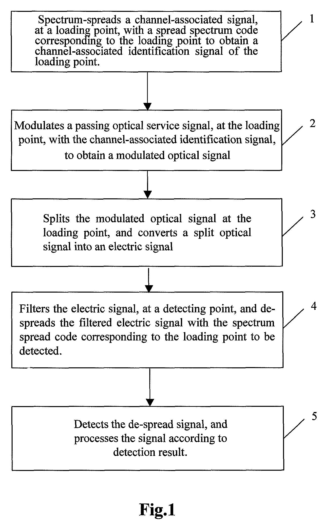
[0030]A method for monitoring a channel-associated optical signal according to an embodiment of the present invention, as shown in FIG. 1, includes the following steps:

[0031]A: Loading

[0032]Step 1: A loading point spectrum-spreads the channel-associated signal, with a spread spectrum code corresponding to the loading point, to obtain a channel-associated identification signal of the loading point;

[0033]Step 2: The loading point modulate a passing optical service signal, with the channel-associated identification signal of the loading point, to obtain a modulated optical signal;
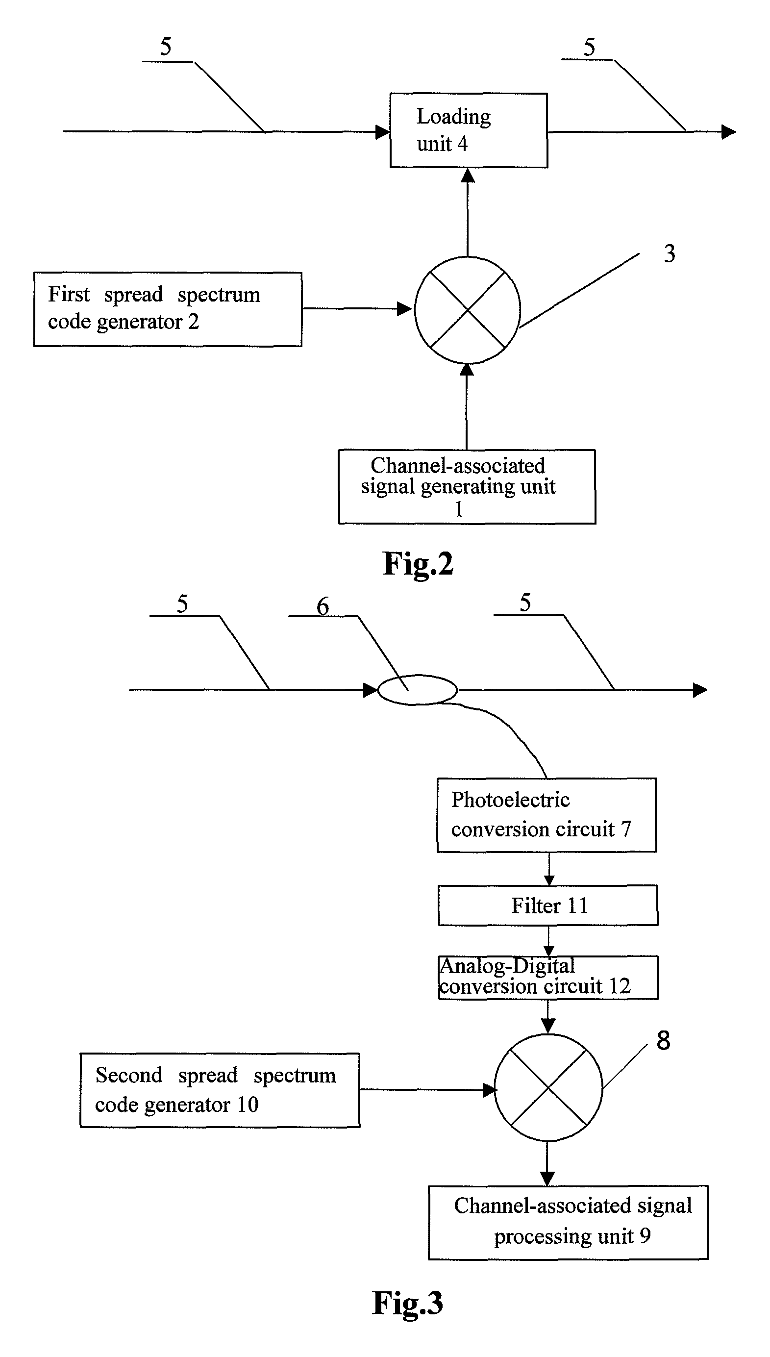
[0034]B: Detecting

[0035]Step 3: A detecting point splits the modulated optical signal, and converts a split optical signal into an electric signal;

[0036]Step 4: The detecting point filters the electric signal, and de-spreads the filtered electric signal with the spread spectrum code corresponding to the loading point to be detected by the detecting point;

[0037]Step 5: The detecting point detects the de-spread ...


PUM


Abstract

A method and apparatus for loading, detecting, and monitoring channel-associated signals are provided. Channel-associated signals are identified with spread spectrum codes in the electrical domain, and after being modulated to an optical service signal at respective loading points separately, the channel-associated identification signals are transmitted in the optical channel along with the optical signal. At any downstream detecting point, passing optical signals can be converted through photoelectric conversion, and the channel-associated identification signals are de-spread. By detecting the channel-associated signals, it is possible to learn about whether the upstream loading point work normally, whether the optical channel operates normally, etc., and thereby to find possible failures, solve problems, and monitor quality parameters of optical signals in real time, and improve reliability of the optical signal transmission.

Description

[0001]This application is a Continuation of PCT International Application No. PCT / CN2006 / 003131, filed Nov. 21, 2006, claiming priority to the Chinese patent application CN No. 200610033905.4 filed on Feb. 21, 2006, entitled “Method and Apparatus for Loading and Monitoring Channel-associated Optical Signals”, the contents of both foregoing applications are incorporated herein by reference in their entirety.FIELD OF THE INVENTION[0002]The present invention relates to the technical field of optical communication, and particularly to a method and apparatus for loading, detecting, and monitoring channel-associated signals.BACKGROUND OF THE INVENTION[0003]The advancement of optical devices greatly promotes the development of optical communications. The rapid advancement of Wavelength Division Multiplexing (WDM) devices and optical amplifiers has made it possible to transmit data at a rate of Terabits per second (Tbps) through a single optical fiber. As the optical transmission technologi...

Claims


Application Information

Patent Timeline
Patent Type & Authority Patents(United States)
IPC IPC(8): H04B10/08H04B10/077
CPCH04B10/0775H04B2210/074H04B2210/072
Inventor LI, CONGQI
Owner HUAWEI TECH CO LTD
Why Eureka
Try Eureka