Setting level of detail transition points

a transition point and detail technology, applied in the field of computer graphics, can solve the problems of increasing the computational cost of rendering, increasing the amount of computations and memory required, and often computationally expensive rendering

Active Publication Date: 2012-10-02
PIXAR ANIMATION
View PDF38 Cites 28 Cited by
  • Summary
  • Abstract
  • Description
  • Claims
  • Application Information

AI Technical Summary

Problems solved by technology

Rendering is often computationally expensive, in terms of the amount of both computations and memory required.
Typically, the computational expense of rendering increases with increased complexity of the scene.
Also, users would often spend considerable amounts of time fine-tuning the values of these parameters to ensure visually satisfactory results.

Method used


Image

  • Setting level of detail transition points
  • Setting level of detail transition points
  • Setting level of detail transition points

Examples


Embodiment Construction

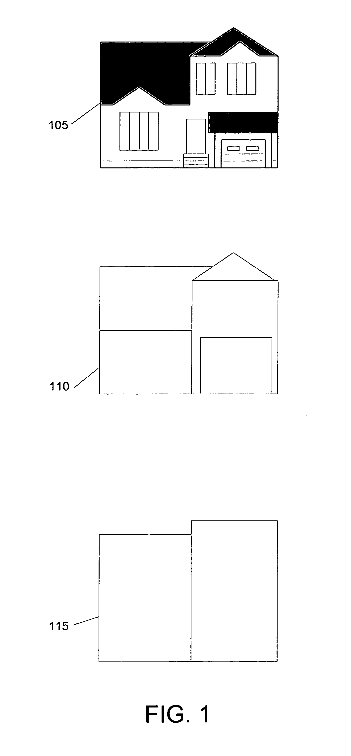
[0016]FIG. 1 illustrates example versions of an object at different levels of detail suitable for use with embodiments of the invention. In this example, the object is a three-dimensional model of a house. A first version 105 of the object is a model of the house with a large amount of complexity. In this example, version 105 of the object includes complex geometric features such as doors and windows. In some applications, version 105 may also include high resolution texture maps and complicated shader programs to specify the color and other optical properties of its surface.

[0017]A second version 110 of the object has less complexity than version 105. In this example, the version 110 of the house object omits many of the details present in version 105. In some applications, the shapes of features in version 105 of the object may be changed to less complex approximations in version 110 of the object. In some applications, optional texture maps and shader programs associated with ver...


PUM


Abstract

Visual representations of different versions of an object are automatically generated and presented to users. Users can compare these visual representations to determine appropriate level of detail transition points based on the visual appearances of different versions of an object. The specified level of detail transition points are converted into level of detail parameter values to be used to select one or more versions of an object for rendering, simulation, or other tasks. The visual representation of each version of an object can include an image sequence of the version at a range of distances from the camera. Each image corresponds to a view of the version at a specific level of detail parameter value. A user interface allows users to view the image sequences associated versions of an object as still images or animation. Users can select images in image sequences as level of detail transition points.

Description

CROSS-REFERENCES TO RELATED APPLICATIONS[0001]This application claims benefit under 35 USC 119(e) of U.S. Provisional Patent Application No. 60 / 811,881, filed Jun. 7, 2006, entitled “Automatic Level of Detail,” which is incorporated by reference herein.BACKGROUND OF THE INVENTION[0002]The present invention relates to the field of computer graphics, and in particular to methods and apparatus for creating, modifying, and using lights and other components to control the attributes and appearance of objects in computer graphics images. Many computer graphic images are created by mathematically modeling the interaction of light with a three dimensional scene from a given viewpoint. This process, called rendering, generates a two-dimensional image of the scene from the given viewpoint, and is analogous to taking a photograph of a real-world scene. Animated sequences can be created by rendering a sequence of images of a scene as the scene is gradually changed over time. A great deal of eff...

Claims


Application Information

Patent Timeline
Patent Type & Authority Patents(United States)
IPC IPC(8): G06F9/44G06T17/00G06G5/00
CPCG06T13/00G06T2210/36
Inventor SMYRL, ELIOTREDDY, MARTIN
Owner PIXAR ANIMATION
Why Eureka
Try Eureka