Water intake structure

a technology of water intake and structure, applied in water cleaning, separation process, filtration separation, etc., can solve the problems of large amount of cooling or other process related water, difficult to economically design a screen or other filter system with sufficiently small openings, and fish may impinge on the surface of the screen

Inactive Publication Date: 2012-10-09
CH2M HILL ENGINEERS
View PDF48 Cites 20 Cited by
  • Summary
  • Abstract
  • Description
  • Claims
  • Application Information

AI Technical Summary

Problems solved by technology

Power plants and other industrial facilities, such as desalination plants, often require large amounts of cooling or other process related water.
Because the size of fish larvae and eggs is relatively small, it is often difficult to economically design a screen or other filter system with sufficiently small openings to prevent entrapment of the fish larvae and eggs, or, in other words, to prevent aqueous organisms from flowing through the cooling system of the plant.
Further, if the velocity of water flow through the filter is too large, fish may become impinged onto the surface of the screen.

Method used


Image

  • Water intake structure
  • Water intake structure
  • Water intake structure

Examples


Embodiment Construction

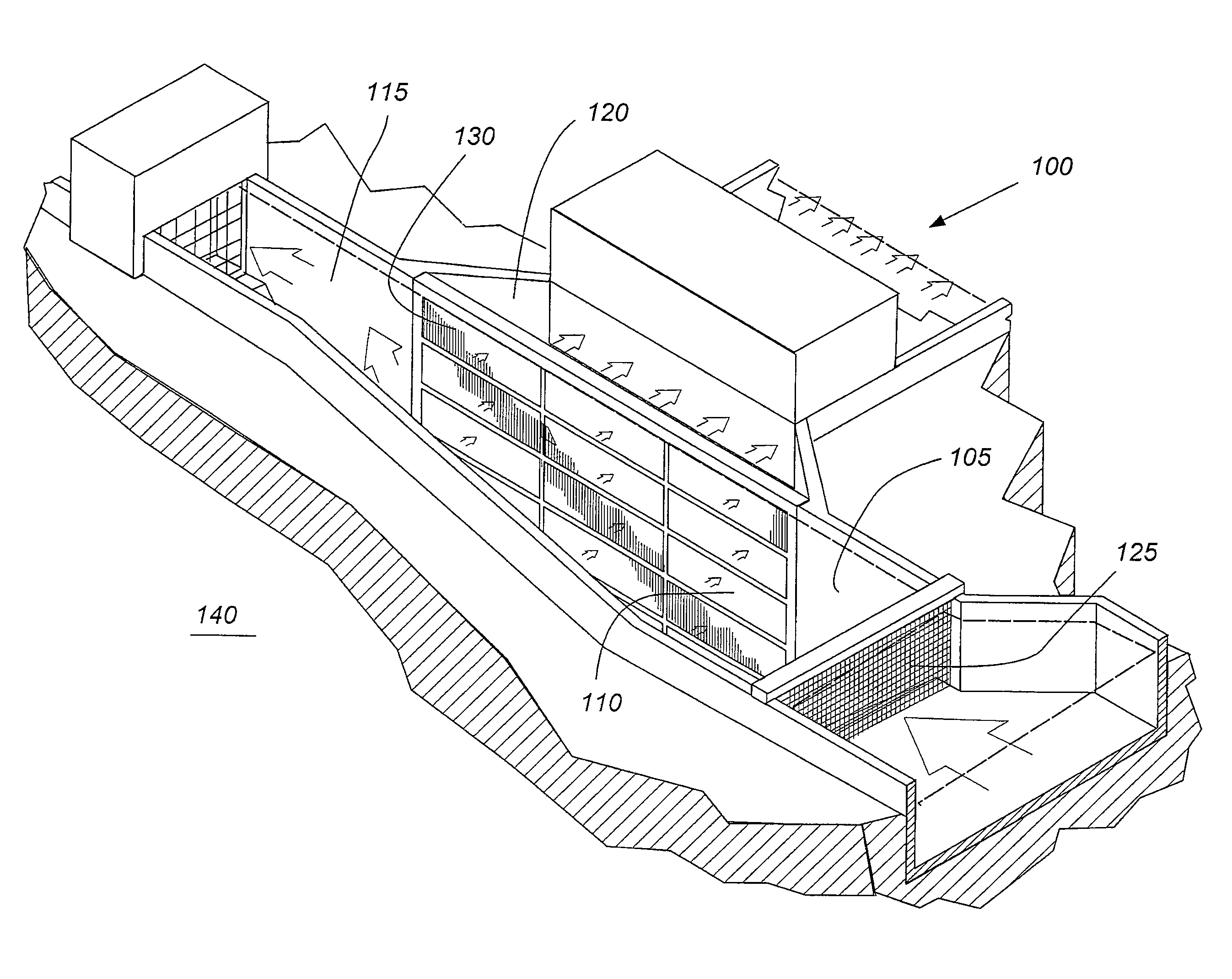
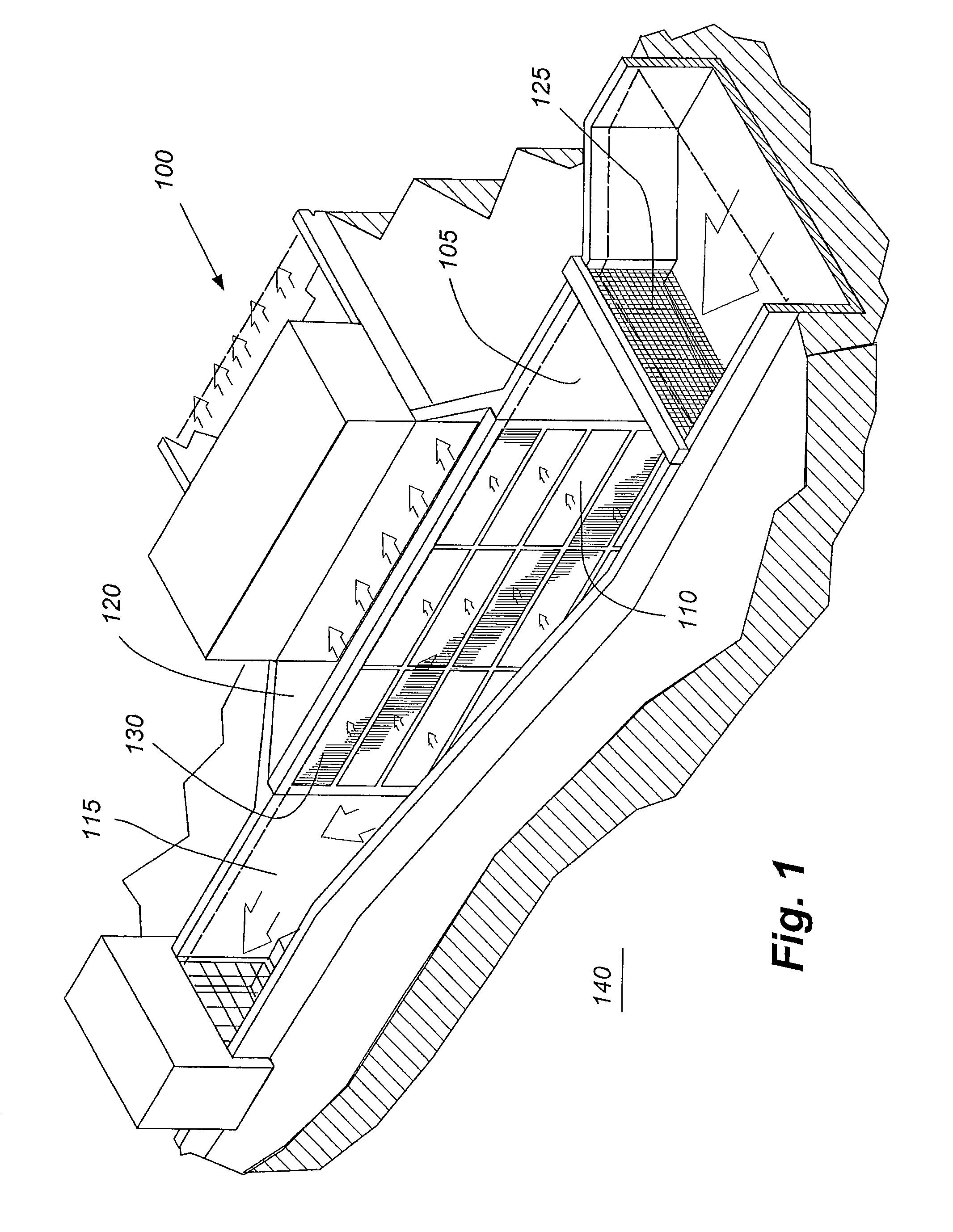
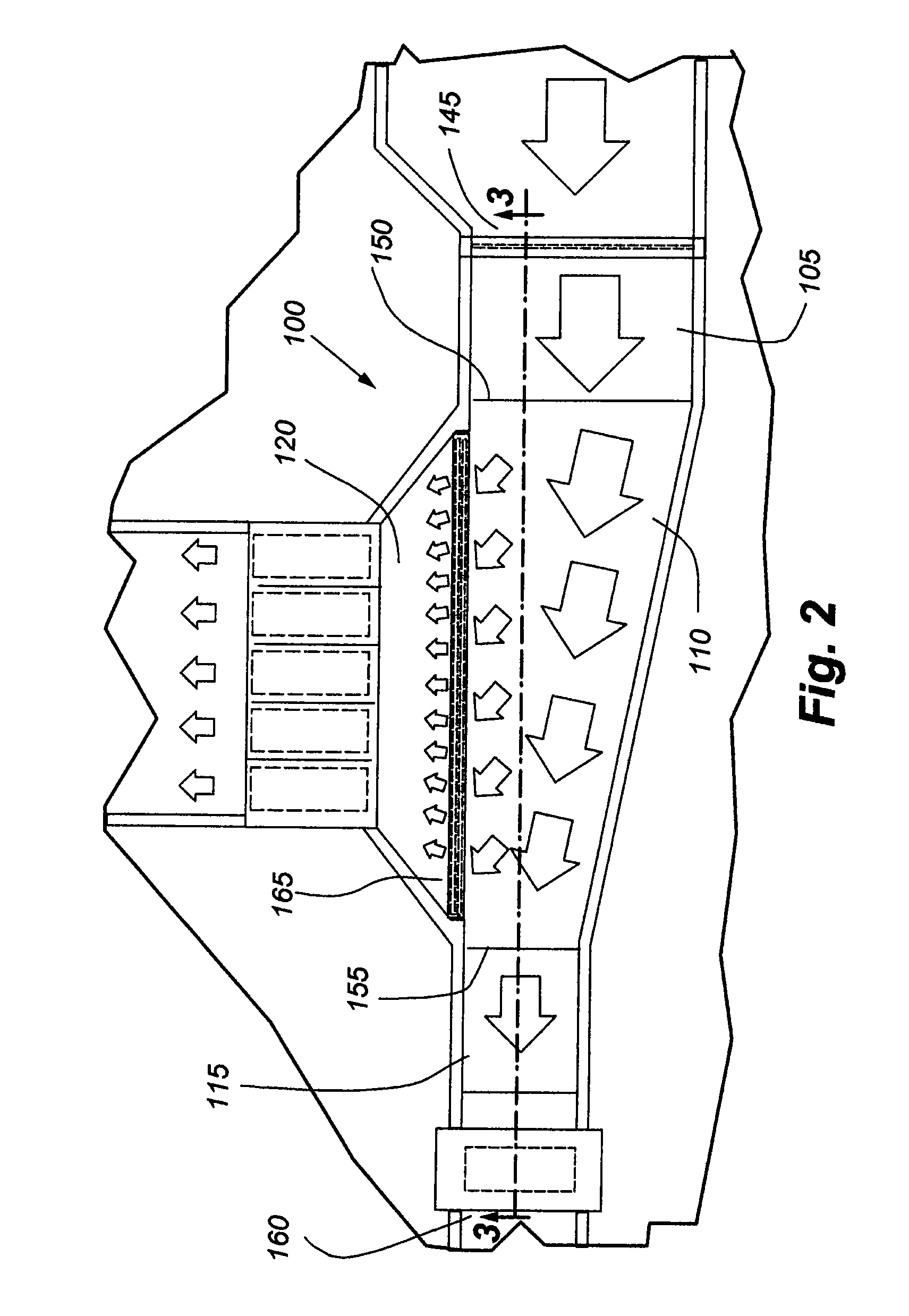
[0014]Described herein are water intake structures for power plants and other industrial facilities. These water intake structures may include an inflow channel, a deep well, an outflow channel, and an intake channel. These structures may further include a trash screen positioned proximate the inflow channel for screening trash and large debris from water drawn from the water source into the inflow channel. These structures may also include a fish screen, such as a wedge-wire or wedge-bar screen or the like, positioned between the deep well and the intake channel to separate fish, fish larvae and fish eggs from water drawn from the deep well into the intake channel. These structures may yet further include one or more circulating or sweep flow pumps positioned proximate the outflow channel. These circulating or sweep flow pumps may be used to maintain a sweep flow through the deep well of the intake structure to help sweep fish, fish larvae and fish eggs away from the fish screen an...


PUM

PropertyMeasurementUnit
angleaaaaaaaaaa
velocityaaaaaaaaaa
depthaaaaaaaaaa

Abstract

Water intake structures for power plants and other industrial facilities may include an inflow channel, a deep well, an outflow channel, and an intake channel These structures may include a fish screen, such as a wedge-wire screen or the like, positioned between the deep well and the intake channel to separate fish, fish larvae and fish eggs from water supplied to the intake channel from the deep well. These structures may further include one or more circulating or sweep flow pumps positioned proximate an outlet of the outflow channel. The sweep flow pumps may be used to maintain a sweep flow through the deep well of the intake structure to help sweep fish, fish larvae and fish eggs away from the fish screen and into the outflow channel.

Description

CROSS-REFERENCE TO RELATED APPLICATIONS[0001]This application claims, under 35 U.S.C. §119(e), the benefit of U.S. provisional application No. 61 / 153,095, entitled “Water Intake Structure” and filed on Feb. 17, 2009, the entire disclosure of which is hereby incorporated by reference herein in its entirety.FIELD OF INVENTION[0002]The present invention generally relates to water intake structures, and more particularly to water intake structures for power plants and other industrial facilities.BACKGROUND[0003]Power plants and other industrial facilities, such as desalination plants, often require large amounts of cooling or other process related water. The required water may be obtained from a large water source, such as an ocean, lake or river. Some of the cooling systems are referred to as once-through cooling systems since the warmed up cooling water is returned to the natural body of water after one pass through the cooling system. Often there is a water intake structure construct...

Claims


Application Information

Patent Timeline
Patent Type & Authority Patents(United States)
IPC IPC(8): E02B5/08E02B8/08
CPCE02B9/04Y02E10/22Y02E10/20Y02A40/60
Inventor FEHER, PETER
Owner CH2M HILL ENGINEERS
Why Eureka
Try Eureka