
Mattress material removal device

a mattress and material technology, applied in the field of mattresses, can solve the problems of laborious, tedious and time-consuming, worn mattress, and damage to the mattress, and achieve the effect of easy removal of the mattress material

Active Publication Date: 2012-10-16
MILLS LUKE
View PDF11 Cites 4 Cited by
  • Summary
  • Abstract
  • Description
  • Claims
  • Application Information

AI Technical Summary

Benefits of technology

[0012]A control device whereby the mattress material removal device provides a means for easily removing the material of the mattress so that only the spring unit or other internal support remains.

Problems solved by technology

Over time the mattress will wear and become damaged and soiled due to stains, odours, lint being removed from the mattress, dust mites, other pests and pet animals.
Removal of the mattress material to date has been achieved by physical hand cutting, ripping and pulling away the material from the underlying spring unit, which can be quite laborious, tedious and time-consuming for the people employed to handle this task.

Method used


Image

  • Mattress material removal device
  • Mattress material removal device
  • Mattress material removal device

Examples


first embodiment

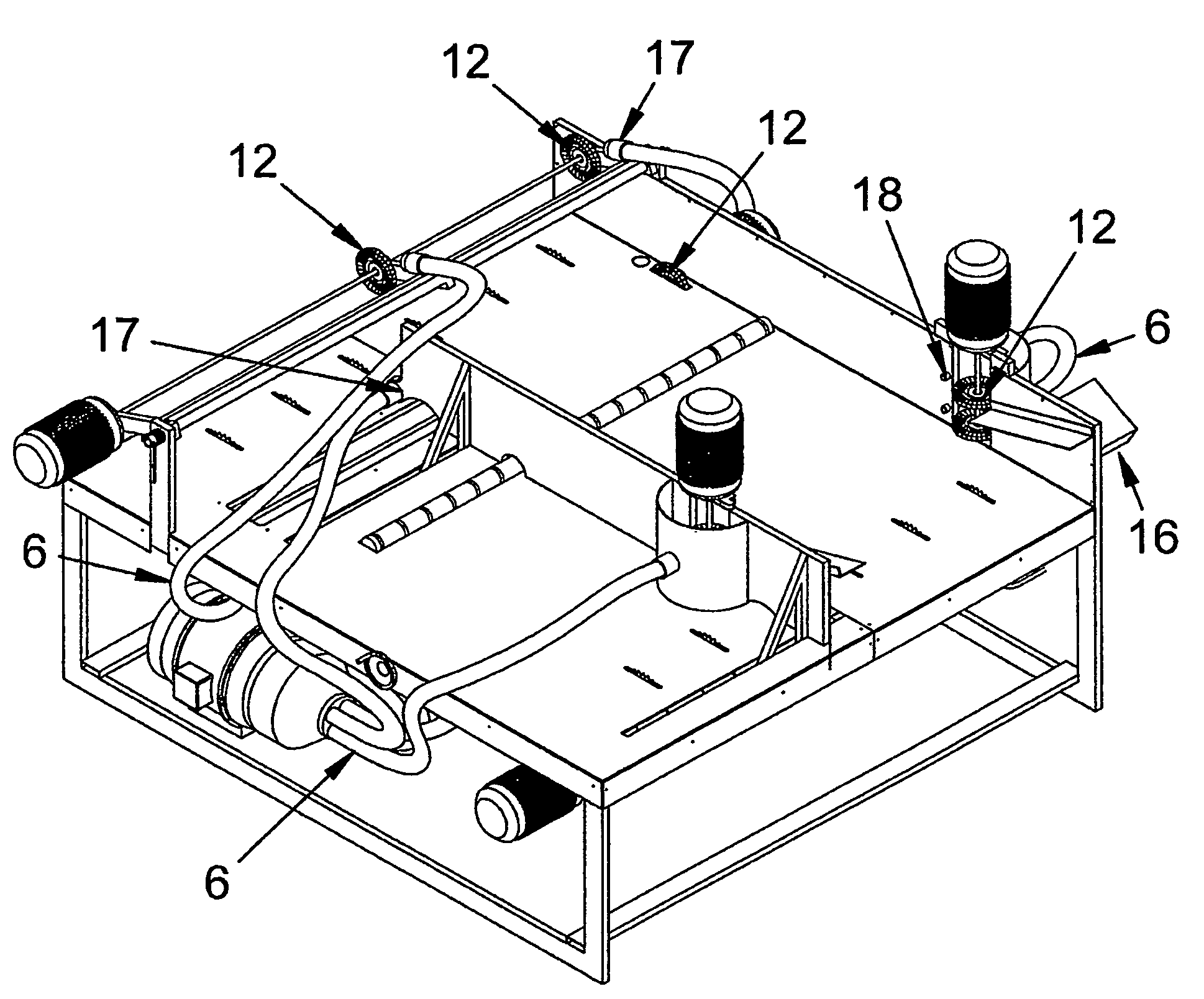
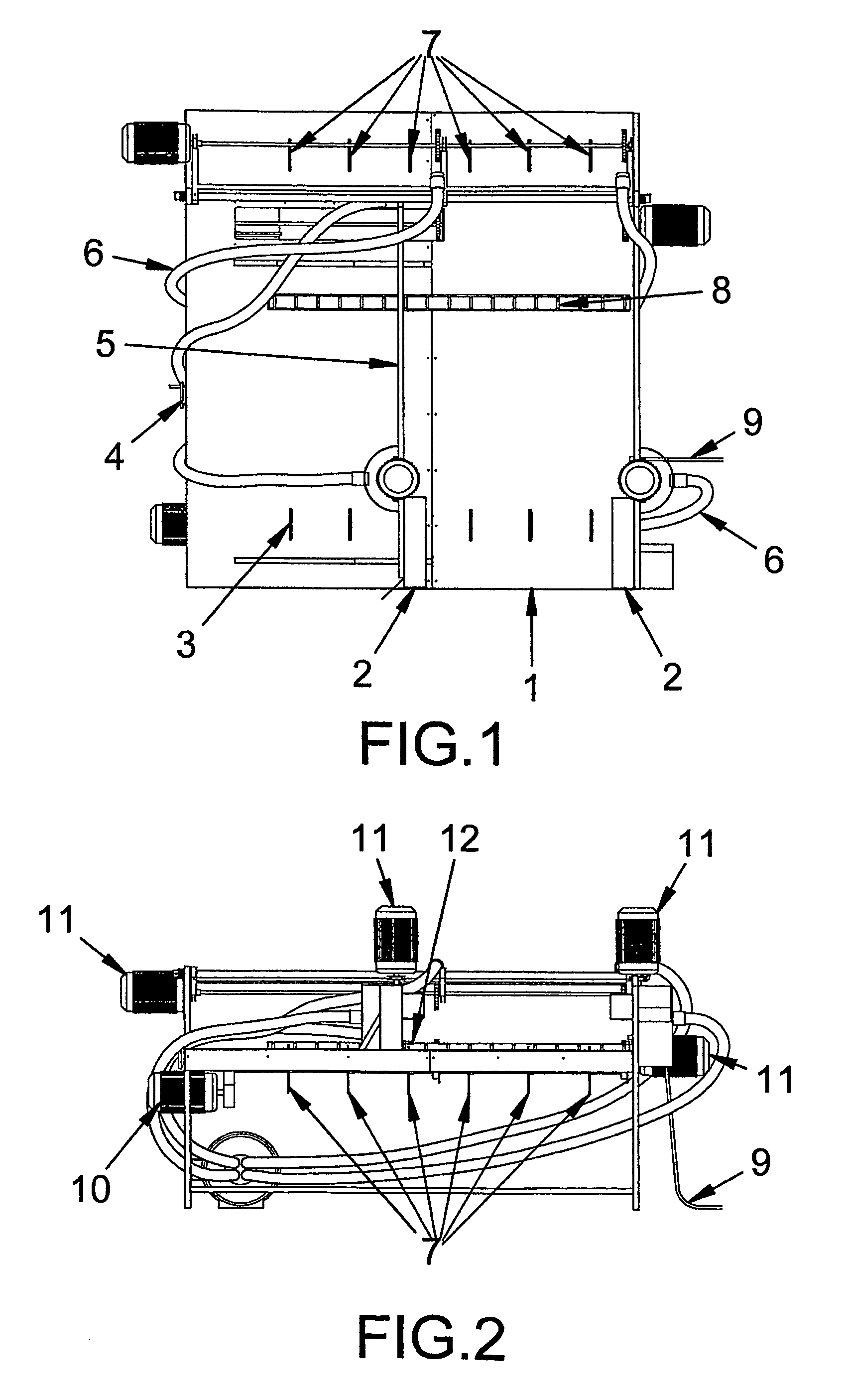
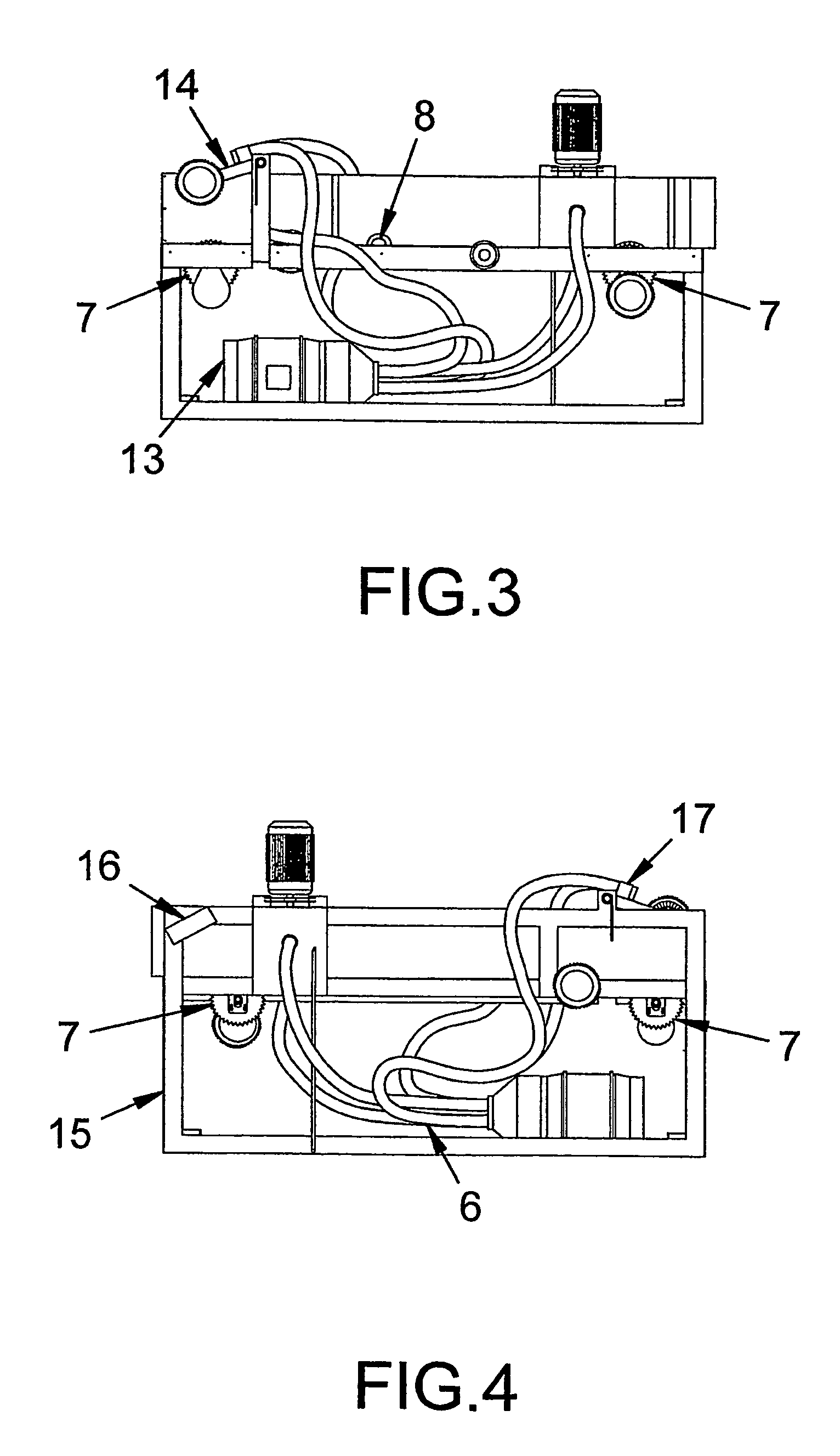
[0033]In a first embodiment, it is envisaged that the mattress material removal device may preferably have provided a fixed base member 15 in FIG. 4, which is adapted to receive the mattress thereon. The base member 15 may preferably be in the form of a base plate 1 in FIG. 1 having a flat surface and suitable dimensions to hold the mattress thereon. It is envisaged that the base member 15 may have provided at least one roller means 8 in FIG. 1 connected thereto which is adapted to assist the mattress to move over base member. In this embodiment, the components of the device may preferably be adapted to move over and around the mattress for removal of the mattress material. It is envisaged that movement of the components will be automated via the control device 16 in FIG. 5. However, any manual or other suitable means of operation may also be employed.

second embodiment

[0034]In a second embodiment, the base member may have provided a conveyor mechanism 7 and 10 in FIG. 2, which is adapted to move the mattress so that it is in contact with the components of the removal device. It is envisaged that operation of the conveyor mechanism 7 and 10 may be controlled via the control device 16 in FIG. 5. In this embodiment, the components are preferably fixed in position passing through a plurality of openings 3 in FIG. 1 within the base plate 1 and the mattress will be moved along the conveyor of the removal device at an adjustable speed, similar to the concept of a car wash, in order to remove the material from the mattress.

[0035]In practice, the mattress is subjected to the brush member 12. As the spinning brush contact the mattress they will work away the material on the mattress, including the material, coir and foam from the top, bottom and sides of the mattress, to leave the underlying spring unit or other internal support exposed so that any remaini...


PUM

PropertyMeasurementUnit
suctionaaaaaaaaaa
speedaaaaaaaaaa
flexibleaaaaaaaaaa

Abstract

A mattress material removal device for bedding mattresses comprising a fixed base member 15 in FIG. 4 with at least one side panel 4 and 5 in FIG. 1, at least one overhead portion 14 in FIG. 3 and at least one guide rail 2 in FIG. 1 adapted to secure and guide the mattress over the base member 15 as it moves through the removal device; at least one brush member 12 in FIG. 5 that makes contact with the top, bottom and side of the mattress; at least one suction member 6 in FIG. 5 positioned in close proximity to at least one brush member 12; at least one sprinkler device that is positioned in close proximity to the brush member 12; a conveyor mechanism 7 and 10 in FIG. 2 which is adapted to move the mattress so that it is in contact with the components of the removal device; a control device 16 in FIG. 5 that has at least one switch which is adapted to activate and de-activate one or more features of the mattress material removal device.

Description

FIELD OF THE INVENTION[0001]This invention relates to mattresses for beds, and in particular, to a mattress material removal device that provides a means for easily removing the material of the mattress so that only the internal spring unit or other internal support remains.[0002]Whilst the invention may be applied to any type of mattress or cushioning or other suitable application, for convenience sake it shall be described herein in terms of a removal device for removing the material of bedding mattresses.BACKGROUND TO THE INVENTION[0003]Most bedding mattresses comprise a spring unit which is overlayed and / or contained within a foam material and coir that is then covered with a fabric material. The foam material and design of the internal spring unit or other internal support may vary between mattresses to achieve different support levels including firm, medium or soft support. Over time the mattress will wear and become damaged and soiled due to stains, odours, lint being removed...

Claims


Application Information

Patent Timeline
Patent Type & Authority Patents(United States)
IPC IPC(8): B23P19/00B23Q15/00B68G15/00
CPCB26D7/18B68G15/00Y10T29/53539Y10T29/53039Y10T29/48Y10T29/53543Y10T29/53Y10T29/49755Y10T29/49751Y10T29/53548
Inventor MILLS, LUKE
Owner MILLS LUKE
Learn More